Annotation
Source file: create-annotations.htm
The Annotation drop-down offers you several different annotation styles that you can add to your project. Annotations are stored in the cad container ![]() .
.
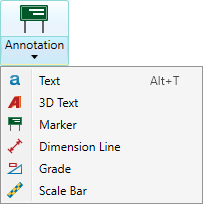
Expand below for details on creating each annotation type.
Tip: To learn how to edit annotations, see Properties.
The Text tool (Alt+T) allows you to label data in a view window with 2D text annotations ![]() . The text maintains its on-screen size and orientation, regardless of view orientation and zoom, so is always legible to the user.
. The text maintains its on-screen size and orientation, regardless of view orientation and zoom, so is always legible to the user.
-
On the Create tab, go to the Create group. From the Annotation drop-down list select
 Text.
Text.
-
On the status bar, enter the text location then click
 , or click on the location in the view window. You will then be prompted for the text.
- Enter the required text then click or press Enter.
The text is saved in the cad ![]() container by default and is displayed in the active view window.
container by default and is displayed in the active view window.

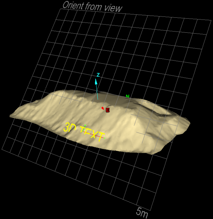
The 3D Text tool allows you to label data in a view window with 3D text annotations ![]() . Unlike the Text tool, 3D text is aligned to the action plane (see Action Plane) and rotated or zoomed like any other 3D object in the scene.
. Unlike the Text tool, 3D text is aligned to the action plane (see Action Plane) and rotated or zoomed like any other 3D object in the scene.
Tip: Set the action plane before creating the text.
Note: Rotating 3D text can cause it to flip directions in the view. The text creation tool provides orientation options to manage text directions.
-
On the Create tab, go to the Create group. From the Annotation drop-down list select
 3D Text.
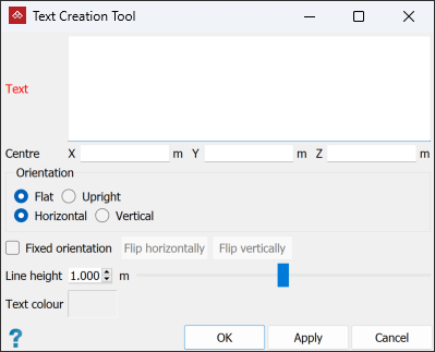
-
Type in the required text.
-
Click in a location field and enter the information or click in the view window at the desired location for the Centre of the text.
PointModeller displays a preview of the 3D text.
-
Select the Orientation options for the best orientation of the text in relation to the action plane.
Tip: If you need a different orientation of the text, you can use the Freehand Rotate tool after creating it. See Transform.
-
Select Fixed orientation to force the text to maintain its orientation with the view’s axes. If Fixed orientation is not selected, the text will flip automatically to maintain readability when you rotate the view.
If Fixed orientation is selected, you can click Flip horizontally and/or Flip vertically to obtain the desired orientation.
-
Enter the required Line height for the text, or use the slider bar to set the value. The maximum possible text size is 2 m.
-
Click OK or Apply to complete.
The 3D text is stored in the cad ![]() container by default and is displayed in the active view window.
container by default and is displayed in the active view window.
The Marker tool allows you to create markers ![]() or signs at strategic locations in the 3D scene, and add attachments relevant to those locations. The marker consists of a text label and a shape.
or signs at strategic locations in the 3D scene, and add attachments relevant to those locations. The marker consists of a text label and a shape.
The attachments allow notes, reports, photographs, diagrams and video files to be easily accessed from a marker, which acts as a visual cue within a 3D scene.
-
To create a marker follow these steps:
-
On the Create tab, go to the Create group. From the Annotation drop-down list select
 Marker.
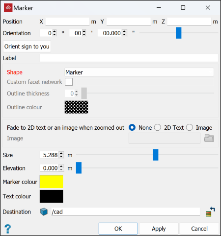
-
Enter the Position for the marker, or click in the view window.
-
Choose Orientation by entering values, dragging the slider or clicking Orient sign to you.
-
Enter the text to be displayed at the marker location in the Label field.
-
Choose the desired Shape for the marker:
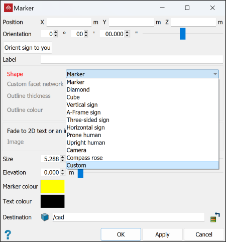
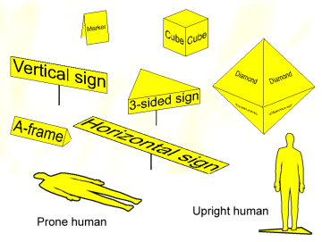

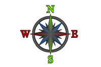
Compass rose
-
For Fade to 2D text or an image when zoomed out, select the option that matches the preferred behaviour when zooming out:
-
None: The marker will diminish and disappear.
-
2D Text: The marker will be replaced with the marker label text, in 2D.
-
Image: The marker will be replaced by the selected image.
Note: As you zoom in, the image or 2D text will disappear. There is a transition range in which both the marker and its replacement will be overlaid.
-
-
Enter a Size for the marker.
-
Enter an Elevation.This suspends the marker at a height above the selected position. Some markers have supporting 'poles', which will grow in height as you increase the elevation parameter.
-
Select the Colours for the marker and its text.
-
Click OK or Apply to complete the process.
The marker is saved in the
cad container by default and is displayed in the active view window.
 -
Adding attachments
You can add attachments to a marker. An attachment can be any type of file. These attachments can also be opened and then viewed, provided Windows recognises the file type and has the appropriate viewer installed.
-
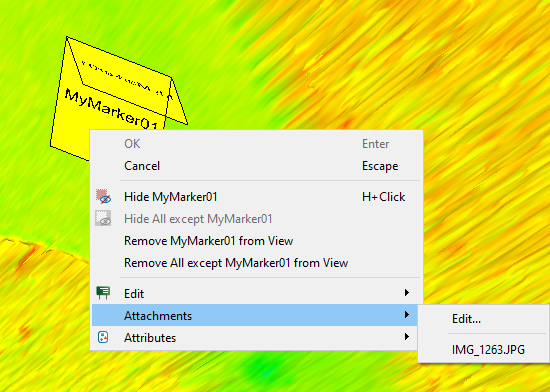
Add attachments by selecting the marker then clicking
 Attachments... in the Properties group of the Annotations ribbon, or by right-clicking the marker and selecting Attachments > Edit.... See View and edit Marker Attachments.
 -
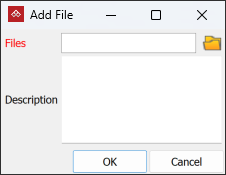
Click to add attachments. A secondary panel, labelled Add File opens.
-
Select to browse for files to attach.
-
Select the files and click Open in the Windows file explorer.
-
Click OK to attach the file to the marker.
-
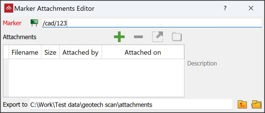
Exit the Marker Attachment Editor.
The Marker Attachment Editor opens.
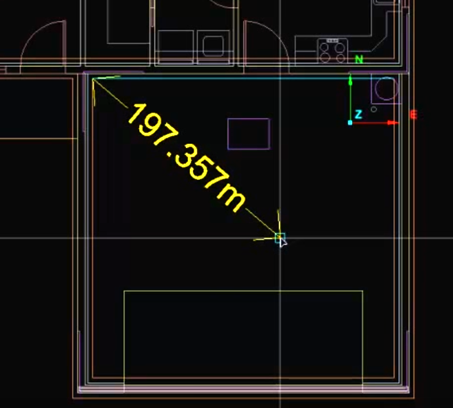
The Dimension Line tool allows you to create dimension lines to annotate dimensions in the view window.
-
On the Create tab, go to the Create group. From the Annotation drop-down list select
 Dimension line.
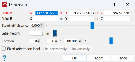
-
Enter the location for Point A (point to measure from), or click the starting point in the view window.
-
Enter the location for Point B (point to measure to), or click the end point in the view window.
Tip: You can use the action plane to assist in placing the dimension lines. Set the action plane then the text and offset of the dimension line will be drawn as close to the orientation of the action plane as the measurement A and B points allow.
Note: If using the mouse, the dimension line, text and stand-off distance are drawn dynamically while dragging the mouse, so you can see how it will be rendered.
You can still follow the remaining steps if you wish to make further manual adjustments. -
Specify the Label height.
-
Choose whether to use a Fixed orientation label. If so, you can adjust the fixed position by clicking Flip horizontally and or Flip vertically. If fixed orientation is not selected, the label will automatically adjust orientation to remain readable as the view is changed.
-
Specify the Stand-off distance, which is the distance between the dimension label and the measurement location.
-
Click OK or Apply to complete.
The dimension line is created and stored in a secondary container in the cad ![]() container by default and is displayed in the active view window. Dimension lines consist of 3D text annotations
container by default and is displayed in the active view window. Dimension lines consist of 3D text annotations ![]() and edge networks
and edge networks ![]() .
.
|
|
|
|
The dimension line and text are drawn dynamically while dragging the mouse. |
The dimension line can be oriented using the action plane. |

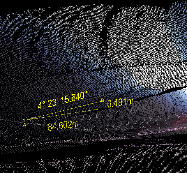
The Grade tool allows you to indicate grades (or slopes) at selected regions in the view window.
-
From the Annotation drop-down list select
 Grade.
Alternatively, from the Query tab, in the Geometry group click
Grade.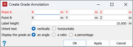
-
Enter appropriate values into Point A and Point B data fields, or snap to points along where the grade is to be measured and displayed in the view window.
The grade will be displayed as text and an accompanying triangle displaying the vertical and horizontal distances between the points specified.
- Set up and adjust the following aspects of the grade annotation display:
- Label height: Input a value appropriate for the overall display.
- Orient text: Select either vertically or horizontally, depending on which suits the main view angle being used.
- Display the grade as: Select from an angle, a ratio, or a percentage according to your requirements.
-
Select OK or Apply to complete the process.
The grade annotation is saved in a secondary container in the
cad container by default and is displayed in the active view window. A grade annotation consists of 3D text annotations  and a right-triangle loop
  .
.
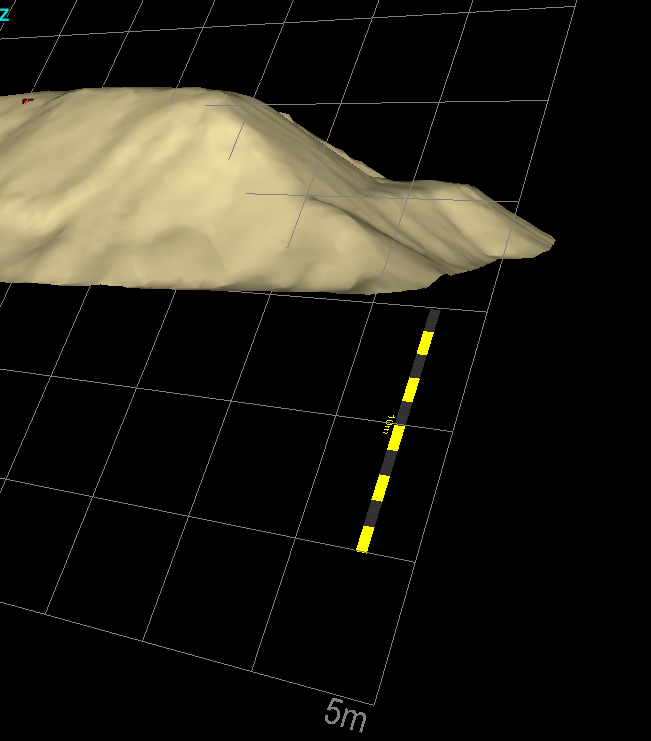
The Scale Bar tool allows you to add scale bars ![]() to view windows to provide a sense of scale when viewing data. Use the action plane as a reference for positioning.
to view windows to provide a sense of scale when viewing data. Use the action plane as a reference for positioning.
-
On the Create tab, go to the Create group. From the Annotation drop-down list select
 Scale bar.
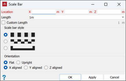
-
Select the Length of the scale bar.
-
Select the Scale bar style.
-
Select the Orientation for the scale bar. The options are with respect to the action plane.
-
Click OK or Apply to finish.
Enter the Location coordinates, or click in the view window for the scale bar's location.
Tip: You can use the action plane to assist in placing the scale bar. Set the action plane then the scale bar will be drawn as close to the orientation of the action plane as the location allows.
A representative scale bar will be displayed in the view window.
The scale bar is created and saved in the cad ![]() container by default and is displayed in the active view window.
container by default and is displayed in the active view window.