Effects
Source file: effects-group.htm
The Effects group contains tools that allow you to change how data are displayed in a view window.

|
|
Coordinate Grid Toggle the coordinate grid on or off. |
|
|
Visibility Editor (V) Toggle the visibility on or off. |
|
|
Surface Render Mode (G) Change the way surfaces are rendered in the view. |
|
|
Side Light Apply lighting from the left or right side, or both. |
|
|
Headlight (Alt+3) Toggle the headlight on or off. |
|
|
Eye-Dome Lighting Toggle eye-dome lighting on or off for best in the view contrast. |
|
|
Juxtaposition View Toggle the juxtaposition view mode on or off. |
Coordinate grid
Click ![]() Coordinate Grid to toggle display of the coordinate grid. The
grid is viewable only from above (looking along the z-
axis) in orthographic projection mode (see Predefined views). The grid is auto-scaling
and displays basic dimensions.
Coordinate Grid to toggle display of the coordinate grid. The
grid is viewable only from above (looking along the z-
axis) in orthographic projection mode (see Predefined views). The grid is auto-scaling
and displays basic dimensions.
Note: Do not confuse the coordinate grid with the ![]() Grid tool on the Create tab, which fits a grid pattern to a surface.
Grid tool on the Create tab, which fits a grid pattern to a surface.
Visibility editor
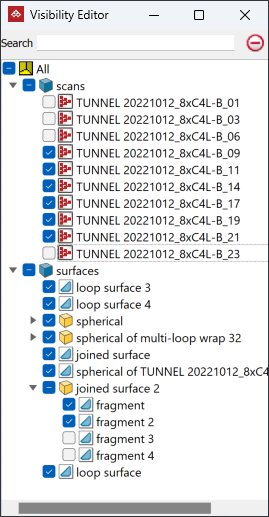
The visibility editor lists the objects currently loaded in the view window and indicates whether they are displayed or hidden. You can control which objects are hidden or visible.
|
|
|
Visibility editor with most objects visible. |
-
To open the visibility editor, either go to the Effects group on the View tab, and select
 Visibility Editor, or press V.
By default, the visibility editor appears as a
pane on the right-hand side of the view
window. By clicking its ![]() button, you can either dock it to the left, or float it
then drag it to a different location. When the visibility editor is floating, you can dock it again by dragging it onto one of the docking targets.
button, you can either dock it to the left, or float it
then drag it to a different location. When the visibility editor is floating, you can dock it again by dragging it onto one of the docking targets.
Note: When redocked, the visibility editor will not reintegrate with the view window, but will appear as a separate pane in the PointModeller workspace. It will, however, remain tied to its original view window.
Use the controls in the visibility editor:
-
Click an object checkbox to toggle visibility of that object .
Note: Where one or more objects in a container are hidden, but at least one is visible, the container's checkbox will display "-" rather than a tick.
-
Click a container checkbox to display or hide all contents of the container.
-
Enter text in the Search field to filter the listed objects.
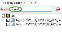
Visibility editor with a search filtering to object names containing
topo of. -
Click the
 button next to the search field to clear the search.
Note: You can also control an object’s visibility via its context menu. Right click on the object, either in the visibility editor or the view window, and select the required option. See Context Menus for more detail.
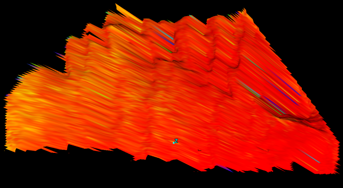
Surface render mode
Surface render mode
sets display of all surfaces ![]()
![]() in the active view window in one of the following forms:
in the active view window in one of the following forms:
-
Solid rendering
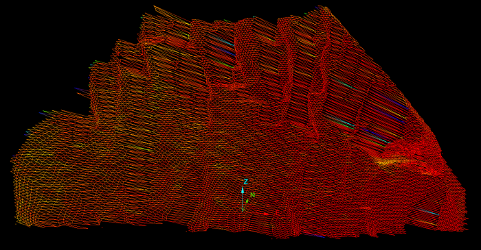
-
Wireframe
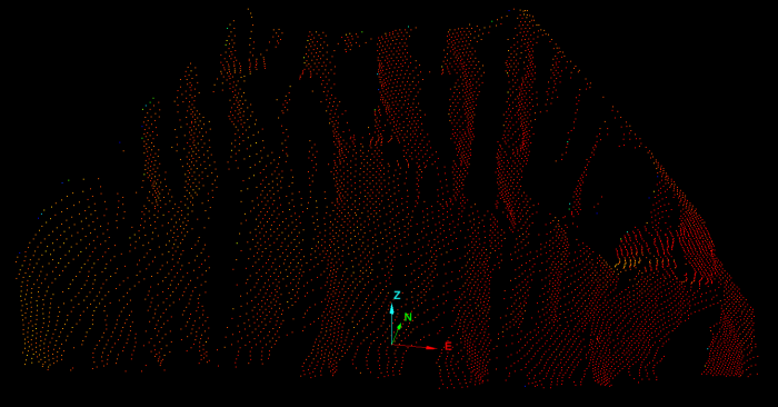
-
Points
From the ![]() Surface Render Mode drop-down list, select one of the above rendering options.
Surface Render Mode drop-down list, select one of the above rendering options.
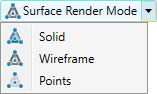
Surfaces will be displayed accordingly.
|
|
|
|
|
|
|
|
|
|
|
|
Lighting effects
Set scene illumination with the following options to enhance object viewing.
Side Light
Switch lighting on or off from both left and right as follows:
-
Select the required combination from the Side Light drop-down.
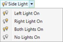
-
Cycle through the options by clicking the Side Light button.
- Press Alt+4 to toggle the left light.
- Press Alt+5 to toggle the right light.
Headlight
Headlight illuminates the view from the camera location and orientation, which is ideal for viewing from a scan origin (see View scan from origin).
Click the ![]() /
/![]() Headlight button or press (Alt+3) to toggle the headlight state.
Headlight button or press (Alt+3) to toggle the headlight state.
Eye-dome lighting
Eye-dome lighting applies enhanced contrast in the view to help you distinguish object features.
Click the ![]() /
/![]() Eye-Dome Lighting button or press (Alt+6) to toggle the eye-dome lighting state.
Eye-Dome Lighting button or press (Alt+6) to toggle the eye-dome lighting state.
You can adjust eye-dome lighting settings to optimise the contrast. See Advanced in Preferences.
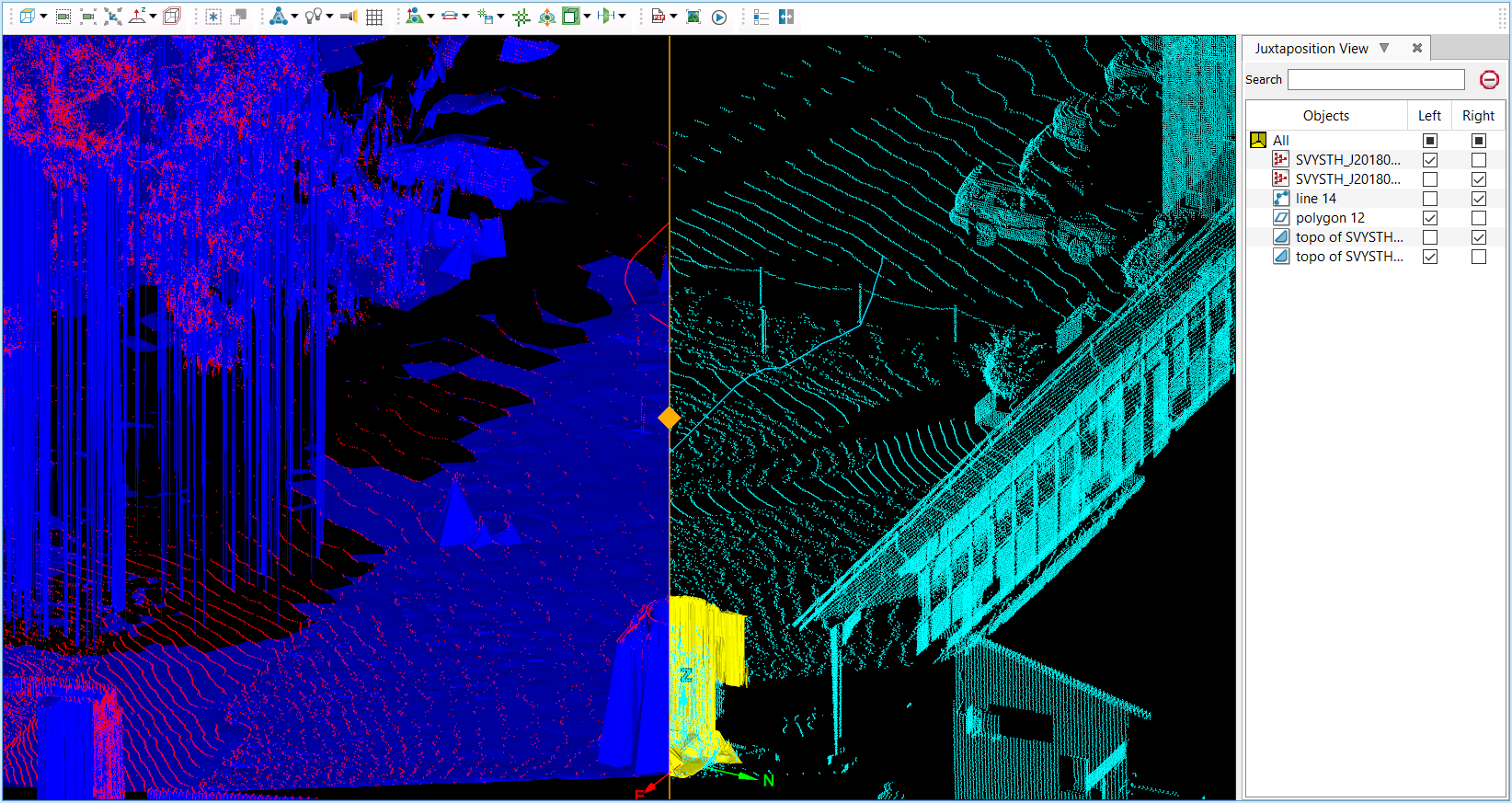
Juxtaposition view
Juxtaposition view enables you to visually compare differences between two or more scans, surfaces, or CAD objects in one view window by dividing the view window into two areas.
-
To open the juxtaposition view, click
 Juxtaposition View.
The view window will split into two view areas separated by a vertical line down the middle. You can drag this line left or right to inspect differences and changes in detail.
Tip: Use the diamond-shaped handle on the middle of the dividing line to drag the line.
A Juxtaposition View editor opens on the right-hand side of the view window. Here you can select the objects to be displayed and hidden on each side of the view window.
Use the controls in the juxtaposition editor, as with the view editor:
-
Click either of an object’s checkboxes to toggle that object’s visibility in the left-hand or right-hand view areas.
-
Enter text in the Search field to filter the listed objects.
-
Click the
button next to the search field to clear the search.
|
|
|
Juxtaposition view splitting a view between two scans of the same area from different surveyed locations, a CAD line and polygon, and two topographic surfaces. |