Preferences
Source file: preferences.htm
You can change PointModeller default settings in the Preferences panel. Settings include language, date, units, registration tolerance, view window, toolbar and more.
To access the Preferences panel:
-
Click
 on the Workbench title bar.
 -
Select
 PointModellerPreferences.
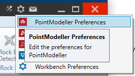
The Preferences panel will open with categories listed on the left-hand side. Click a category to view and change its settings as appropriate.
Expand sections below for detail on each preferences category.
Locale
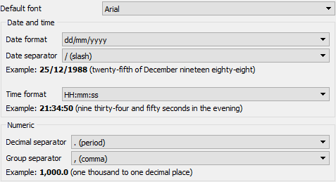
Note: See Workbench Preferences (General) for instructions on setting the primary language.
Units
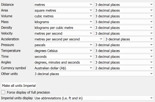
PointModeller units (metric or imperial) default to the computer’s region settings, with precision to three decimal places. For example, if the language is set to English (Australia), a distance of 1.25 m will be displayed as 1.250 m. However, if the language is set to English (United States), the same distance will be displayed as 4.101 ft.
For each listed measurement you can select your preferred units and display precision from the drop-down lists.
If the Distance units are set to metres, with one decimal place precision, the above distance will be displayed as 1.3 m, regardless of the computer’s settings.
In the Other units field, set the precision for all values not individually defined. For example, if the field is set to two decimal places, and a standard error value of 0.061234 is to be displayed, the value will appear as 0.06.
From the Imperial units display drop-down, select whether to display feet and inches as abbreviations or symbols. For example, 6 ft 2 in or 6' 2".
If a unit is set to Full precision (from the bottom of the precision drop-down), it will be displayed using scientific notation at its full precision.
When Force display of full precision is selected, all values will display at full precision, regardless of their unit settings.
Note: 64-bit floating point value precision is typically 16 decimal places.
Coordinate systems
Manage coordinate systems and preferences.
General
-
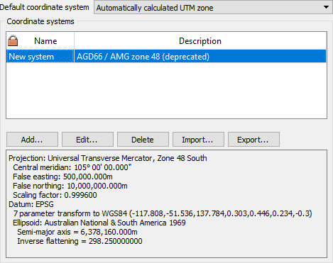
Default coordinate system: Select a coordinate system from the drop-down list to be assigned automatically to imported scans.
-
Add...: Click to populate the Coordinate systems table with coordinate systems that can be selected later using the Define coordinate system and Convert coordinate system tools. See Coordinates for full instructions.
-
Edit...: Select a coordinate system to modify, then click to edit.
-
Delete: Select a coordinate system, then click to delete.
-
Import...: Click, then browse, select and accept a system to import.
-
Export...: Select a coordinate system, then click Export.
Transforms
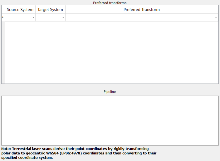
Preferred transforms: When there are coordinate systems defined in the General tab (see above), they will appear in the Source System and Target System lists. To set a default transform, select a source and target system then select a transform from the Preferred Transform list.
Pipeline: Modify the transform process steps as required.
Tip: Set up a transforms in pairs, as System 1 > System 2 and System 2 > System 1.
Registration
View windows
Configure the default view window appearance, mouse behaviour and more.
Note: Changes to view window preferences only apply to new view windows.
General
-
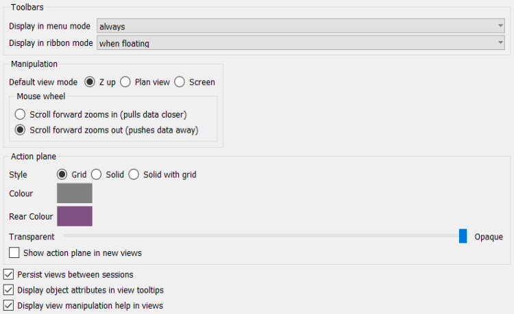
Toolbars: Choose when view window toolbars are displayed in either ribbon mode or menu mode (see Workbench Preferences (General)).
-
always: Toolbars are always displayed.
-
never: Toolbars are always hidden.
-
when floating: Toolbars are displayed when the view window is floating, but not when docked.
-
-
Manipulation: Choose the default manipulation mode and mouse wheel behaviour.
-
Select Z up, Plan view or Screen. See Set manipulation mode.
Note: Look from mode is not available here because it requires the user to select a location.
-
Select preferred scroll wheel zoom direction.
Tip: Scroll forward zooms in matches other Windows apps.
-
-
Action plane: Set the default action plane characteristics.
-
Style: Choose to display the action plane as a grid, solid or combination.
-
Colour: Set the default colour of the plane.
-
Rear colour: Set a different colour to indicate when the plane is being viewed from behind.
-
Transparent-Opaque: Adjust the slider to the preferred level of transparency.
-
Show action plane in new views: Select to display the action plane automatically in new view windows.
-
-
Persist views between sessions: If selected, PointModeller will launch with views in their last-opened state.
-
Display object attributes in view tool-tips: If selected, an object’s attributes (if any) will appear as a tool-tip on mouse over.
-
Display view manipulation help in views: If selected, a temporary tip will appear at the top of the active view window when an applicable tool is clicked.

Properties
-
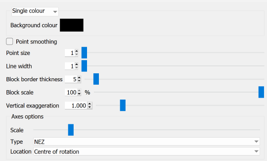
Choose a background colouring style from the drop-down list, as follows:
-
Single colour: The background is a single, uniform colour. Click the swatch and select a background colour from the palette.
-
Screen gradient: The background transitions from one colour at the bottom to another at the top, regardless of view direction. Click the swatches and select bottom and top background colours from the palettes.
-
Sky gradient: The background transitions with the Z axis. Select a predefined gradient style from the Available gradients drop-down list.
-
-
Point smoothing: Select to display rounded points. This is most noticeable with increased point size.
-
Point size: Set the default point display size.
-
Line width: Set the default line display width.
-
Block border thickness: Set the default display block border thickness.
-
Block scale: Set the default block display scale.
-
Vertical exaggeration: Stretch or compress data visualisation in the Z direction. Set the exaggeration scale for optimal viewing.
-
Axes options: Choose the appearance and location of axes.
-
Scale: Adjust the slider to change the size of axes.
-
Type: Select the style of axes from the drop-down.
-
Location: Put the axes at the centre of rotation or in one corner of the view.
-
Picking and snapping
-
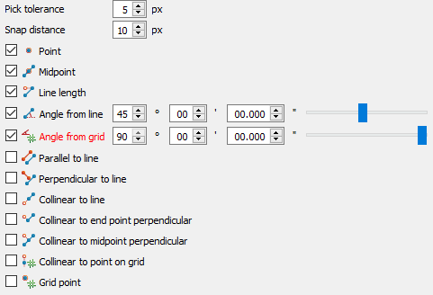
Pick tolerance: Set the maximum distance in pixels from a point to pick it with the mouse pointer.
-
Snap distance: Set the maximum distance in pixels from a point at which snapping will occur.
-
Snap targets: Select targets to activate by default. With the angle targets, also set the required snapping angles.
Advanced
-
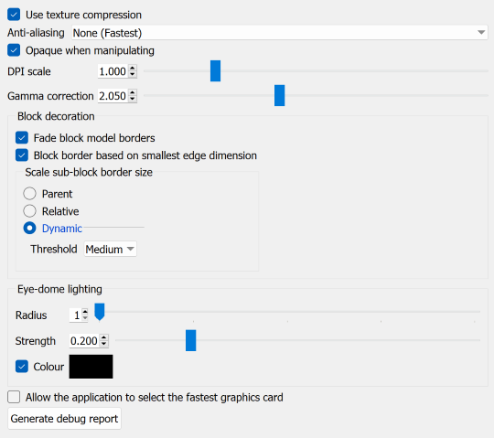
Use texture compression: Compress image data before sending to the GPU. Select if processing very large images.
-
Anti-aliasing: Improve view quality by rounding sharp edges. Select from the options in drop-down list.
-
Opaque when manipulating: Increases performance when manipulating views by suspending translucency.
-
DPI scale: Resize geometry
-
Gamma correction: Adjust to improve display precision where pixel errors occur.
-
Block decoration: Set default block model appearances.
-
Eye-dome lighting: Adjust eye-dome lighting parameters as required.
-
Radius: Increase the radius to extend the reach of the shading effect.
-
Strength: Adjust the strength of the shading effect.
-
Colour: Select and choose a shading colour from the palette. Deselect to shade with the background colour.
-
-
Allow the application to select the fastest graphics card: Select if Windows settings default to a slower card.
Features
-
To create features that you can apply to objects, follow these steps:
-
Select an option from the Profile drop-down list:

-
Select Default to create features and attributes that will be set as the default features and attributes for your objects.
- Select a profile name, if one exists (in the example above Demo), to list the features that are in that profile (in the example above Demo_1).
- Select New... to create a new profile for storing and sorting new features. Enter a name and click OK.
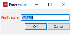
PointModeller will add the new profile to the drop-down list.
Tip: Click Delete on the far right to remove the selected profile.
Note: The Default profile cannot be deleted.
-
-
Click Add...: to create a new set of features and attributes.
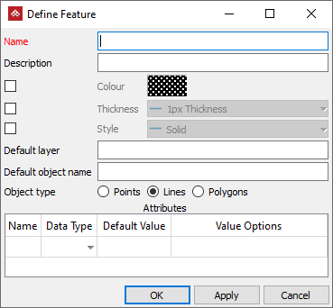
A blank Define Feature panel will open to create your new features.
-
Enter a feature name and configure the remaining settings as required.
-
Name: Enter a name for the feature. Required.
-
Description: Enter a description of the feature. Optional.
-
Colour: Select the checkbox and click the colour swatch; select a colour. Optional.
-
Thickness: Select the checkbox then select a line thickness from the drop-down list. Optional.
-
Style: Select the checkbox then select a line style from the drop-down list. Optional.
-
Default layer: Enter a layer name. Optional.
-
Default object name: Enter a new object name, which will be given to objects created with this feature. Optional.
-
Object type: Select the object type that the feature will apply to. Required.
Note: When a feature is selected for use, Draw group tools not pertaining to the associated object type are disabled and style options are locked.
-
Attributes: Set additional attributes to be assigned to the object. Optional.
-
- Click OK to accept the changes and close the panel.
- Click Apply to save the changes.
-
-
To edit an existing feature, select it in the Features list and click Edit..., then repeat steps 2 to 5 above.

These features can now be accessed either on the Create tab, in the Draw group, from the Feature drop-down, or on the Edit tab, in the Properties group, to be applied quickly.
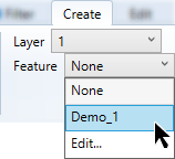
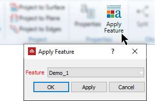

The remaining buttons provide the following operations:
- Remove: To remove the selected feature sets.
- Import...: To import a feature shared from another PC.
- Export...: To export a feature for use on another PC.
Geotechnical
Configure geotechnical tool default parameters.
General
-
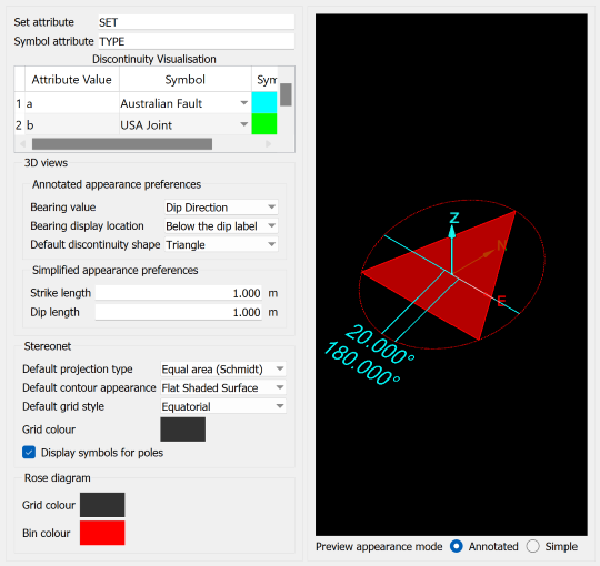
Set attribute: Specify the name applied to discontinuity sets when copying them to
.tek.isisdatabases. If a.tek.isisdatabase contains a column with the same name, that column will be populated with this attribute. -
Symbol attribute: Specify the default discontinuity attribute name to control the appearance of discontinuity symbols. Values for this attribute can be paired with specific symbols in the Discontinuity Visualisation table, following. Configure the values in the Discontinuity Attributes tab (see below).
-
Discontinuity Visualisation: Pair discontinuity symbols with attribute values. Double-click the Attribute Value field to enter a value then select a symbol from the Symbol drop-down and a colour from the Symbol Colour palette.
Tip: With the Discontinuity Visualisation table configured, you can easily apply symbols to differentiate between discontinuities with the Edit Attributes tool.
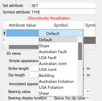
Attribute symbols list.
-
3D Views: Configure the default appearance of discontinuities in standard 3D view windows.
Annotated appearance preferences: Set default rendering of annotated discontinuity symbols.
-
Bearing value: The displayed bearing can be either Dip Direction or Strike , where dip direction = strike + 90 °.
-
Bearing display location: Choose where to display the bearing from Below the dip label or On the strike line.
-
Default discontinuity shape: Choose the shape to display the discontinuity from Triangle, Square, Rectangle and Circle.
Simplified appearance preferences: You can display discontinuities as simple ellipses rather than using symbols.
-
Strike length: Specify the axis length in the strike direction.
-
Dip length: Specify the axis length in the dip direction.
-
-
Stereonet: Configure the default appearance of discontinuities in stereonet views.
Note: Changes to stereonet preferences only apply to new view windows.
-
Default projection type: Choose the default stereonet projection between Equal area (Schmidt) and Equal angle (Wulff).
-
Default contour appearance: Choose the default contour appearance between Wireframe and Flat Shaded Surface.
-
Default grid style: Set the default grid style as Equatorial, Polar or None.
Note: You can change these appearances as required with the corresponding buttons on the Stereonet View tab or the stereonet view window toolbar.
-
Grid colour: Click to choose a default grid colour from the palette.
-
Display symbols for poles: Select to show poles as symbols or clear to show poles as points.
-
-
Rose diagram: Choose default colours for rose diagram grids and bins.
-
Preview appearance mode: Preview how discontinuities will be displayed as either Annotated or Simple.
Discontinuity Attributes
-
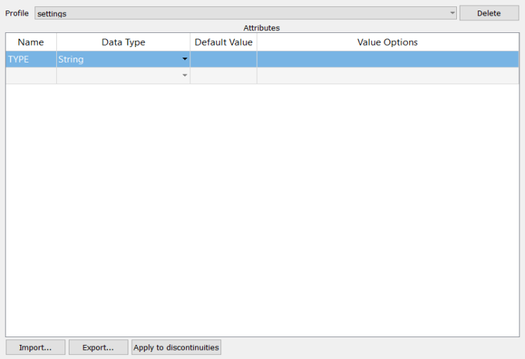
To create attributes that you can apply to discontinuities, follow these steps:
-
Select an option from the Profile drop-down list:

-
Select Default to create attributes that will be set as the default attributes for your discontinuities.
- Select a profile name, if one exists (in the example above Demo), to list the attributes that are in that profile (in the example above Demo_1).
- Select New... to create a new profile for storing and sorting new attributes. Enter a name and click OK.

PointModeller will add the new profile to the drop-down list.
Tip: Click Delete on the far right to remove the selected profile.
Note: The Default profile cannot be deleted.
-
-
Create new attributes as follows:
-
Double-click in the first empty Name field and type a name for the attribute.
-
Select a data type from the Data Type drop-down.
-
Enter a default value in the Default Value field.
-
Enter a semicolon-delimited list in the Value Options field if you require selectable alternative values. These values will be available in the Add/Set Object Tags panel, via the Edit Attributes tool (see Edit Attributes).
-
- Click OK to accept the changes and close the panel or click Apply to save the changes, but leave the panel open.
-
-
To apply an attribute to discontinuities, do the following:
-
Select the attribute in the Attributes box.
-
Select the discontinuities in the view window or project explorer.
-
Click Apply to discontinuities.
-
Click Yes in the subsequent message box, which indicates that the operation cannot be undone.
-
-
To edit an existing attribute, double-click the field you want to edit and enter or select the new details.
The remaining buttons provide the following operations:
- Import...: To import attributes in a
.jsonfile from another source. - Export...: To export attributes in a
.jsonfile for use in another project.
You can edit or remove attributes applied to any discontinuities with the Edit Attributes tool on the Position and Filter ribbon tab. See Edit Attributes.
Stereonet View properties
Note: Changes to view window preferences only apply to new view windows.
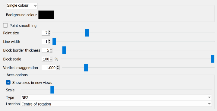
-
Choose a background colouring style from the drop-down list, as follows:
-
Single colour: The background is a single, uniform colour. Click the swatch and select a background colour from the palette.
-
Screen gradient: The background transitions from one colour at the bottom to another at the top, regardless of view direction. Click the swatches and select bottom and top background colours from the palettes.
-
Sky gradient: The background transitions with the Z axis. Select a predefined gradient style from the Available gradients drop-down list.
-
-
Point smoothing: Select to display rounded points. This is most noticeable with increased point size.
-
Point size: Set the default point display size.
-
Line width: Set the default line display width.
-
Block border thickness: No effect in stereonet views.
-
Block scale: No effect in stereonet views.
-
Vertical exaggeration: No effect in stereonet views.
-
Axes options: No effect in stereonet views.
Advanced
Configure various advanced settings.
-
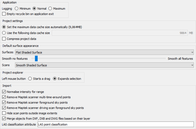
Logging: Choose the level of logging detail. The data log is used to assist with fault diagnosis when using the Contact Maptek tool. See Customer Support.
-
Empty recycle bin on application exit: Select to clear the PointModeller recycle bin when closing the application.
Set the data cache memory allocation. Make automatic or allocate a specific amount of memory.
It can be beneficial to decrease the cache size when:
- Other applications are running and need more memory.
- Running multiple copies of the program concurrently.
- Your computer runs out of memory.
It can be beneficial to increase the cache size when Cache is full error messages appear.
Select Compress project data if you need to save drive space. This setting will only take effect after restarting the application.
Set the default look of the surface appearance.
-
Surfaces: Choose how new surfaces will appear from the following:
-
Flat Shaded Surface
-
Smooth Shaded Surface
-
-
Smooth no/all features: Set the level of feature smoothing between nothing smoothed and everything smoothed. When set halfway, flat areas are smoothed, but sharp features remain crisp.
-
Scans: Choose how new surfaces will appear from the following:
-
Flat Shaded Surface
-
Smooth Shaded Surface
-
Choose how the left mouse button behaves.
-
Starts a drag: Click and hold on an object to drag that object to new locations.
-
Expands selection: Drag over multiple objects to select them.
Filtering options to be applied to scan data during import.
-
Normalise intensity for range: Alter the intensity when first imported so points with the same reflectivity at different ranges contain the same intensity values.
-
Remove Maptek scanner multi-time-around points: Run a filter over scans when first imported to remove multi-time-around points. Points will be deleted and set to invalid returns.
Note: This filter will only run on first import of scans from the Maptek Gen 3 series or newer scanners.
-
Remove Maptek scanner foreground sky points: Run a filter over scans when first imported to remove foreground sky points. Points will be deleted and set to invalid returns.
Note: This filter will only run on first import of scans from Maptek 8xxx series or newer scanners.
-
Remove Maptek scanner driving scan foreground sky points: Run a filter over driving scans when first imported to remove foreground sky points. Points will be deleted and set to invalid returns.
Note: This filter will only run on first import of scans from Maptek 8xxx series or newer scanners.
-
Hide scan points outside image extents:
-
If not selected, with scans which are coloured photographically on import, points not covered by the photo are coloured by greyscale intensity instead.
-
If selected, those points not covered by the scan’s photo are hidden; only photographically coloured points are visible.
-
-
Merge objects from DXF, DXB and DWG files based on their layer: Objects belonging to the same layer will be merged into a single object when importing .dxf, .dxb or .dwgfiles.
LAS classification attribute: Enter a point attribute name to be applied to LAS classification file types.
Reports
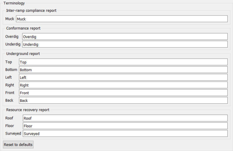
Enter new text into relevant fields then click Apply.
Click Reset to defaults to restore original terminologies
Photogrammetry
-
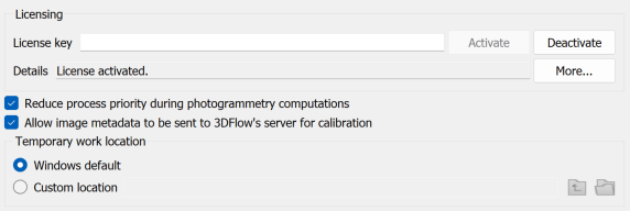
Licence key: Enter or paste the licence key code then click Activate.
-
Deactivate: Click when finished with the photogrammetry module (important when using a shared licence).
-
More: Click to see licence information.
-
Reduce process priority during photogrammetry computations: Select to prioritise other processes over photogrammetry.
-
Allow image metadata to be sent to 3DFlow's server for calibration: Deselect if you do not want photographic metadata shared outside of PointModeller.
-
Temporary work location: Specify the drive location for temporary work files.
Manage preferences
Manage preferences provides some basic housekeeping functionality such as saving, exporting and importing configurations, and resetting all options to default.
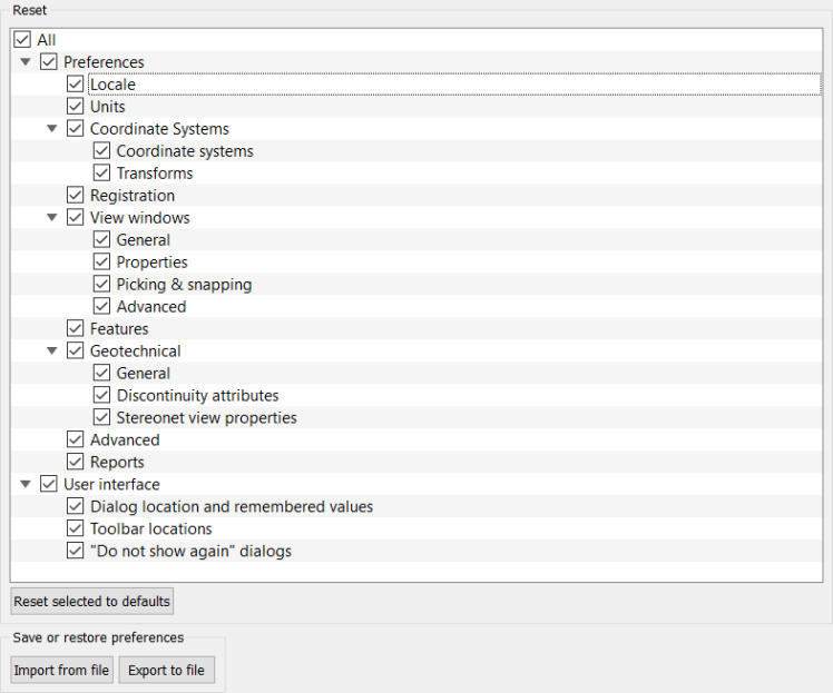
Note: Data persistence in software extends to placement of panels and windows. When the software is opened, panels will appear in the same position as the previous session. This can cause a problem if, for example, a panel was placed on a second monitor which is no longer in use.
-
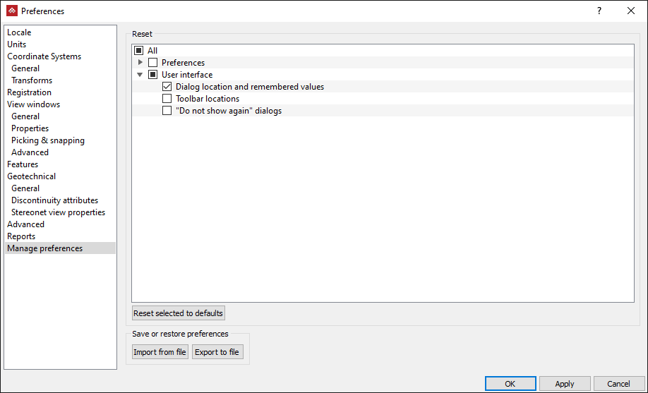
From the Manage preferences view User interface options by clicking the expander
 .
. -
Select Dialog location and remembered values.
-
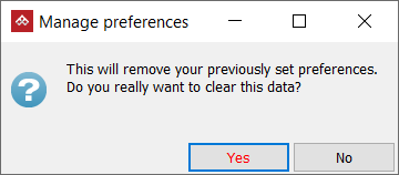
Click Reset selected to defaults button followed by Yes on the confirmation panel.
-
Click OK to exit the preferences options.
Use the above procedure to reset any of the other preference categories to default.
You can also save or recall preferences configurations with the Export to file and Import from file buttons.

