New
Source file: create-new-photogrammetric-reconstruction.htm
The New tool allows you to create a new photogrammetry project.
Note: You will achieve the best photogrammetry results with photos taken following the recommended photography rules. See Photogrammetry.
Note: You cannot perform photogrammetry on a single file; you need to select at least two files. Typically one would use at least ten, and often more than 100.
Create a new photogrammetry project as follows:
-
On the Photogrammetry tab, click
 New.
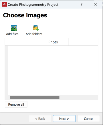
New.The Create Photogrammetry Project panel will open on the Choose images page.
-
Add the required image files to the Input image files field in one of the following ways:
-
Drag the image files in bulk from a Windows file explorer directly to the Input image files field.
-
Click
 Add files..., navigate to the image folder, select the folders containing the image files and click OK.
 -
If the image files are in multiple folders, click
 Add folders..., navigate to the parent folder, select the folders containing the images and click OK. PointModeller will import all images in the selected folders into the project.
Tip: In the search field of the file selection dialog, type
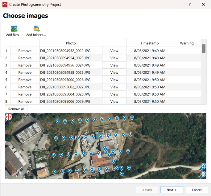
kind:imageto find and list all images in the chosen location and its subfolders.The images will be listed in the next panel and those with GPS data will be marked on a satellite image of the area.
 Tip
TipYou can manipulate the tool panel as follows, for easy viewing:
- Resize the tool panel to see the whole table without scrolling.
- Pan the preview map, or marquee to select specific images on the map. Click the button in the top-left corner of the preview to toggle between modes:
 Pan mode
 Selection mode
-
-
Remove any unwanted images from the list by clicking the corresponding Remove buttons.
Tip: You can preview an image by clicking the corresponding View button in the list. The image will open in a new Workbench Image Viewer window.
-
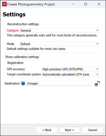
Click Next > to advance to the Settings page.
Choose the required reconstruction settings:
-
Select the reconstruction category according to the descriptions:
General For reconstruction projects where other options don’t apply. Aerial/Nadiral For reconstructing a top-down view scenario, typically a UAV drone-acquired dataset. Urban For reconstructing buildings, façades, or scenarios that are shot in an urban setting. You can use this category for small objects instead of the Surface scan category if you are mixing different types of photos, especially if the whole dataset is not shot from the same distance. Surface scan For reconstructing surfaces close up (e.g., terrain or ground). Vertical structure For reconstructing telecommunication towers or other thin vertical structures from drones. -
Select the mode, depending on the required level of detail:
Fast Reduced resolution, bundle adjustment iterations and number of keypoints: faster than default. Default Default settings suitable for most use cases. Deep Increased bundle adjustment iterations, number of keypoints and camera matches. Slower than the default setting, this mode should be used when you are losing cameras in Default mode.
-
-
From the GPS accuracy drop-down, select the option that better matches the accuracy of the GPS metadata in the image files.
Note: If no images containing GPS information are selected, the Review Images page will not show either the map view or the GPS accuracy options.
- From the Target coordinate system drop-down, select the coordinate system that the GPS positions must be converted to, if different from default. If the required coordinate system is not listed, select New system... and set it up (see Coordinates > Set up a coordinate system manually).
-
PointModeller automatically loads camera calibration settings read from the 3Dflow server, based on the camera model, read from photographic metadata.
Note: If you do not want photographic metadata sent to 3Dflow, you can disable this in PointModeller preferences. See Preferences > Photogrammetry.
 Expand if camera calibrations do not provide the required level of accuracy.
You can adjust the settings if supplied values do not produce the required level of accuracy. Click Show calibration settings to view and edit.
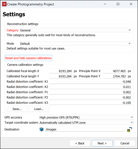
Important: Only make camera calibration adjustments if you are confident of the correct values.
The camera calibration settings received from the 3Dflow database might not be accurate for your camera due to natural manufacturing variations within tolerances. You can calibrate any affected camera online using the 3Dflow Zephyr Free application, as follows:
-
Download and install 3Dflow Zephyr Free from 3DF Zephyr.
-
Launch 3Dflow Zephyr Free.
-
From the Utilities menu, in the Images sub-menu, select Camera Calibration....
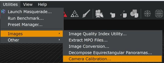
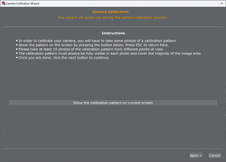
The camera calibration wizard will open.
-
Follow the wizard instructions.
When the calibration tool has finished running, you will receive calibration settings in an .xml file.
-
Load the calibration settings into PointModeller by clicking Load... on the Create Photogrammetry Project panel.
Tip: Click Reset and hide camera calibrations to restore the original calibration settings.
Tip: Click Save to save manually applied new calibration settings as an .xml file for future use.
-
-
By default the output will be placed in a container named for the folder of the source images, inside the
imagescontainer . To store the output in a different container, drag the container from the project explorer to the Destination field.
 -
Click Next > to advance to the Batch processing page.
-
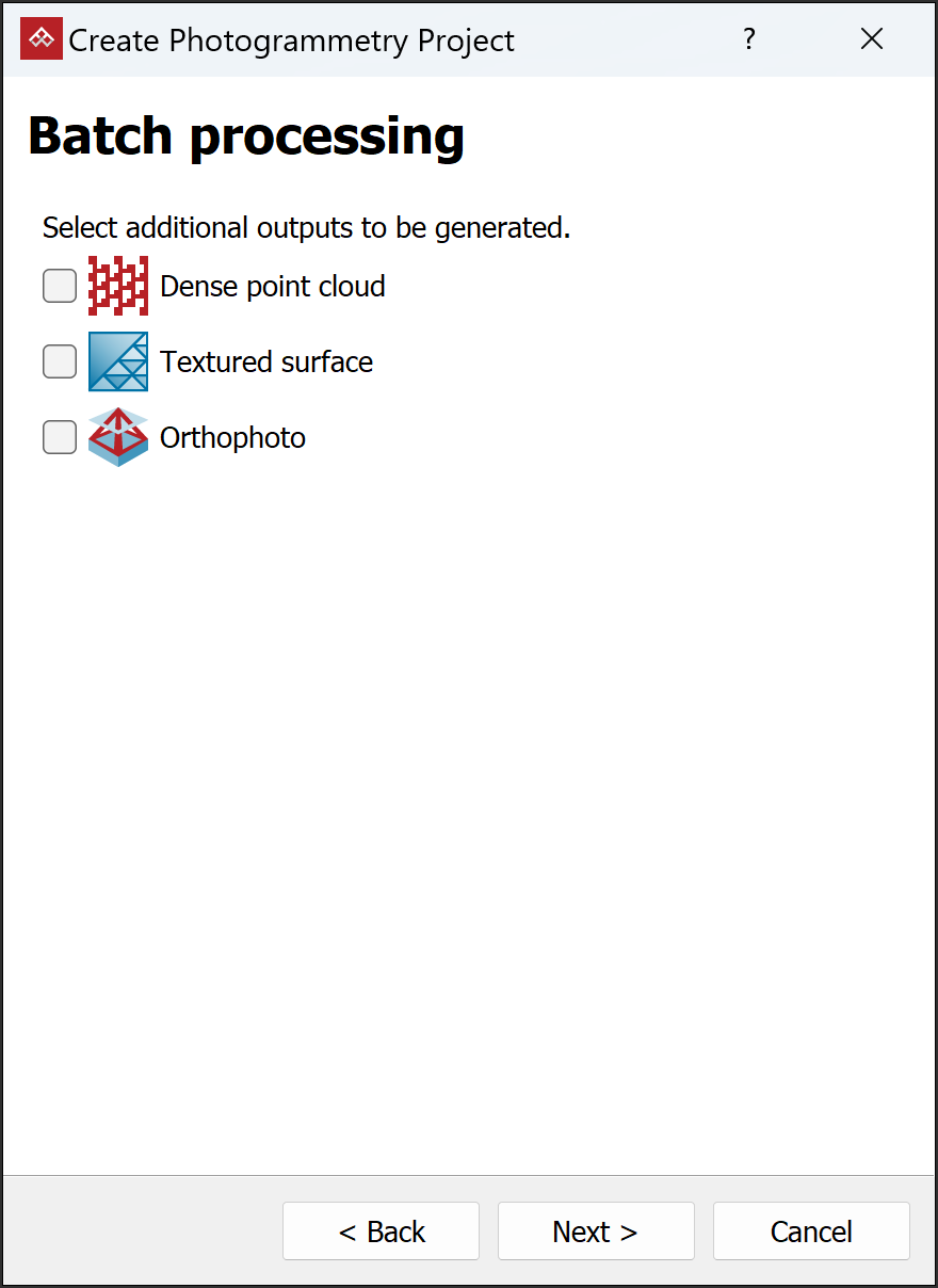
If any of the selected images contain GPS information, you will have the option of batch-processing the remaining photogrammetry tools, excluding Register Reconstruction. Select the tools you wish to run.
Tip: Because these tools run sequentially, you only need to select the one to be processed last.
Note: If you need to do further registration of the images, leave the batch processing tools unselected.
-
Click Next >.
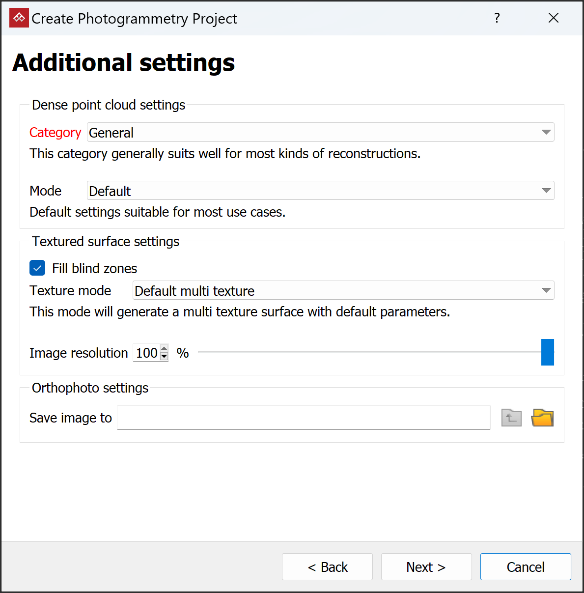
Expand if you selected any additional outputs on the batch processing page
The Additional settings page will appear.
-
Select category and mode settings for each selected stage. See Create Dense Point Set, Create Textured Surface and Export Orthophoto for more detail.
-
Set a destination folder and name for the orthophoto image.
-
Click Next >.
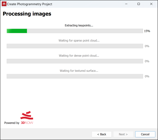
The tool will run, generating a sparse point cloud, followed by the selected batch processes.
Created objects are saved in the chosen or default container and folder and displayed in the active view window.
-
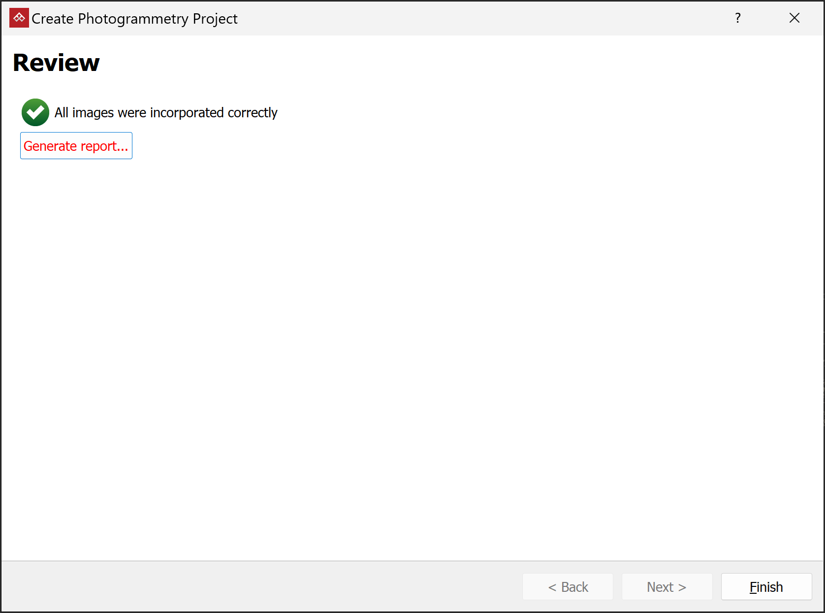
-
(Optional) Click Generate report... to produce a report with basic parameters of the project, processing results and accuracy evaluations.
Note: The report is generated as an HTML file (
.html) to be viewed off line in a web browser. From there, you can print the report or save it in your preferred document format, such as PDF.
View a sample photogrammetry report. -
Click Finish to close the tool.
