Extract Discontinuities
Extract discontinuities
enables you to identify individual regions containing planes of interest,
and then automatically highlighting and selecting all similar planar regions
over the rest of the surface or area of interest. A key application
would be to select one fault plane and the procedure will automatically
identify all others in the view that meet the selection criteria.
-
On the Geotechnical ribbon tab navigate to the Dip and Strike group and select
 Extract.
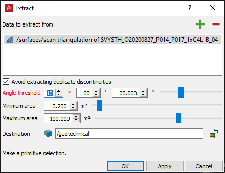
- Select
points on the surface that represent the plane of interest.
- Angle threshold defines the angles between which other planes will be considered similar to the original plane of selection.
- Minimum area defines the minimum area to define the similar planes.
- Maximum area defines the maximum area to define the similar planes.
- Click the Apply button to begin the process of finding similar planes or the OK button to begin the process then exit the panel when finished. The number of planes discovered will be displayed in the panel.
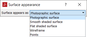
Note: Discontinuities can be displayed in different formats to suit the operator's preferences. Select the discontinuities in the geotechnical container and apply Colour > Surface appearance. Options include Annotated, Flat shaded surface and Wireframe.

An example of configuring discontinuities as Annotated.
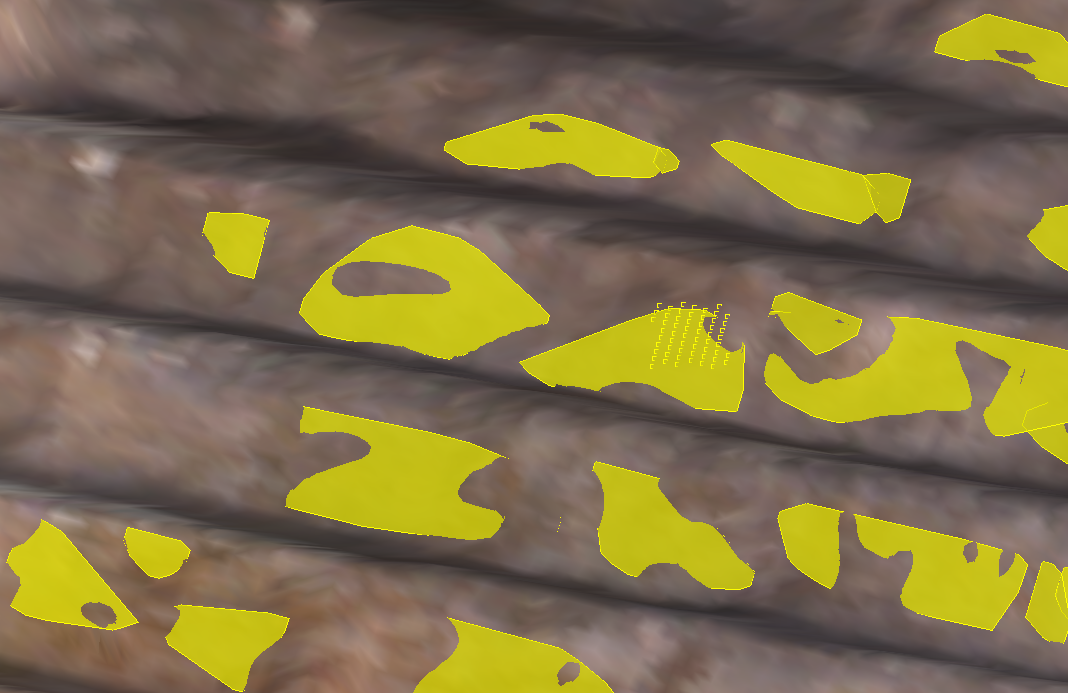
An example of configuring discontinuities as Flat shaded surfaces without annotations.