Kinematic Analysis
Kinematic analyses are conducted using stereonets on a collection of poles(normals of planes) or plane intersections selected from the discontinuities of a rock face. The analyses help to identify the kinematic feasibility for sliding, wedge and toppling failures in an excavated face. The components examined include slope dip, slope dip direction, daylight envelope, slip limit, lateral limits, polar friction cone and planar friction cone.
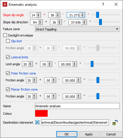
Use the Failure zone drop-down list to select the type of failure to be analysed. Fill in the appropriate values for the relevant criteria in the Kinematic analysis tool panel and examine the resulting stereonet to see if any poles or intersections are in critical zones. A kinematic analysis object will be saved into the stereonet container specified in the Destination stereonet field.
The following tables and diagrams will provide background information explaining the types of failures, critical zones and examples of relevant stereonet diagrams.
Note: You will need to ascertain likely friction angles and lateral limits appropriate to the rock faces and materials being investigated.
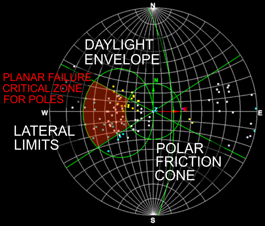
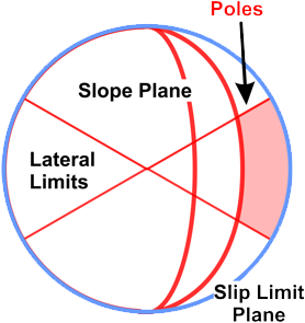
Below is a typical Kinematic analysis plot on a stereonet.
Kinematic analysis components
The Kinematic analysis components required for the analysis of each of the failure mechanisms is summarised in the table below.
| KINEMATIC ANALYSIS COMPONENTS | TYPICAL REPRESENTATION OF COMPONENTS ON STEREONETS | FAILURE MECHANISMS | |
|---|---|---|---|
| Note: Orientation and scale can be different according to actual planes under investigation. | |||
|
|
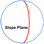
Slope dip Slope of the pit wall or main rock face. Measured down from horizontal. |
Great circle plotted from the Slope dip and Slope dip direction of the pit wall or main rock face. |
PLANAR WEDGE FLEXURAL DIRECT |
|
Slope dip direction Direction the slope runs directly s directly downwards. Measured from North. |
PLANAR WEDGE FLEXURAL DIRECT | ||
|
|
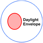
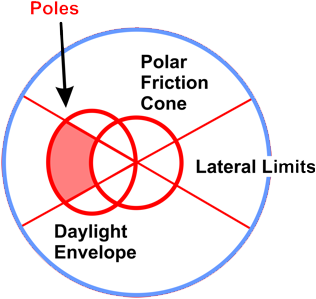
Daylight envelope Determined from Slope dip and Slope dip direction. The envelope contains the set of poles (normals) of planes at a flatter angle than the Slope Plane and which could possibly slide off if unconstrained. |
|
PLANAR |
| KINEMATIC ANALYSIS COMPONENTS | TYPICAL REPRESENTATION OF COMPONENTS ON STEREONETS | FAILURE MECHANISMS | |
|---|---|---|---|
| Note: Orientation and scale can be different according to actual planes under investigation. | |||
|
|
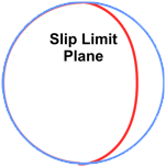
Slip limit Greater circle representation of the plane at which friction slipping will occur. Poles (normals) closer to the outside perimeter of the main circle are steeper and will slide or topple.
|
|
FLEXURAL |
|
Slip limit dip angle = pit slope angle - friction angle Slip limit dip direction = same as pit slope |
|||
|
|
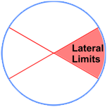
Lateral limits Identifies planes in the same general direction as the main slope face dip direction. Planes outside these limits generally do not initiate a sliding or toppling failure. |
|
PLANAR FLEXURAL DIRECT |
|
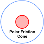
Polar friction cone Planes with poles outside the Polar friction cone are steep enough to overcome friction and start sliding. |
|
PLANAR DIRECT | |
|
|
Defect plane dip > friction angle (assuming friction only) |
||
|
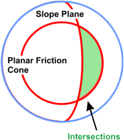
Planar friction cone Plane intersections that occur within the Planar Friction Cone are steep enough to overcome friction and start sliding. |
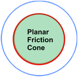
|
WEDGE DIRECT | |
|
|
Line of intersection dip (between 2 discontinuities) > friction angle (assuming friction only) |
||
| KINEMATIC ANALYSIS COMPONENTS | TYPICAL REPRESENTATION OF COMPONENTS ON STEREONETS | FAILURE MECHANISMS | |
|---|---|---|---|
| Note: Orientation and scale can be different according to actual planes under investigation. | |||
|
|
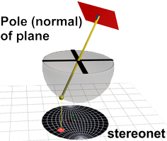
Poles (normals) Point formed by the vector which is perpendicular to the plane of interest discontinuity). |
|
PLANAR FLEXURAL DIRECT |
|
Intersections Point formed by the vector at the intersection of planes of interest (discontinuities). |
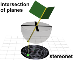 |
WEDGE DIRECT | |
Failure analysis
The following table displays the critical stereonet regions and point types (poles or intersections) relevant to the analysis for the various failure mechanisms.
| TYPE OF FAILURE | CRITICAL REGION ON STEREONET | |
|---|---|---|
| Note: Orientation and scale can be different according to actual planes under investigation. | ||
|
|
PLANAR FAILURE
Dislodgement and downwards sliding of blocks or layers along single common failure planes. |
|
| PROCEDURE | ||
|
|
Any critical poles occur outside the Polar friction cone, inside the Daylight envelope and between the Lateral limits |
|
| TYPE OF FAILURE | CRITICAL REGION ON STEREONET | |
|---|---|---|
| Note: Orientation and scale can be different according to actual planes under investigation. | ||
|
|
WEDGE FAILURE
Dislodgement and downwards sliding of blocks along two intersecting, common failure planes. |
|
| PROCEDURE | ||
|
|
Any critical intersections occur inside the Planar friction cone and towards the outside (shallower) than the main slope plane. |
|
| TYPE OF FAILURE | CRITICAL REGION ON STEREONET | |
|---|---|---|
| Note: Orientation and scale can be different according to actual planes under investigation. | ||
|
|
FLEXURAL TOPPLING
Forwards flexing and downwards sliding of steeply slanting blocks or layers. |
|
| PROCEDURE | ||
|
|
Any critical poles occur towards the outside of the Slip limit plane (steeper) and between the Lateral limits. |
|

| TYPE OF FAILURE | CRITICAL REGION ON STEREONET | |
|---|---|---|
| Note: Orientation and scale can be different according to actual planes under investigation. | ||
|
|
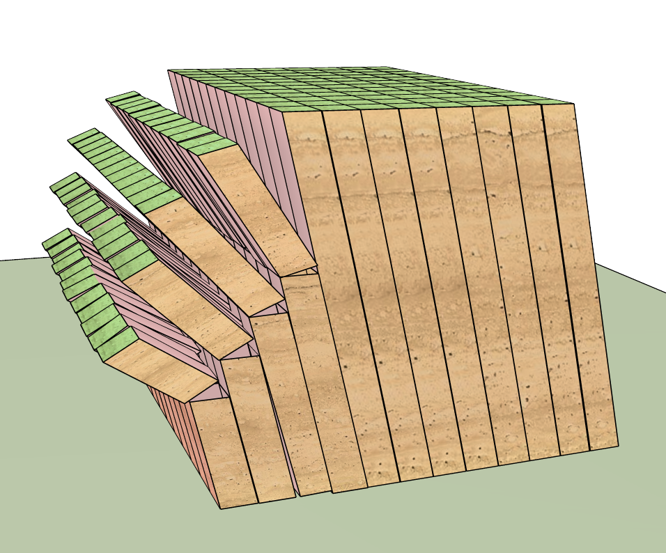
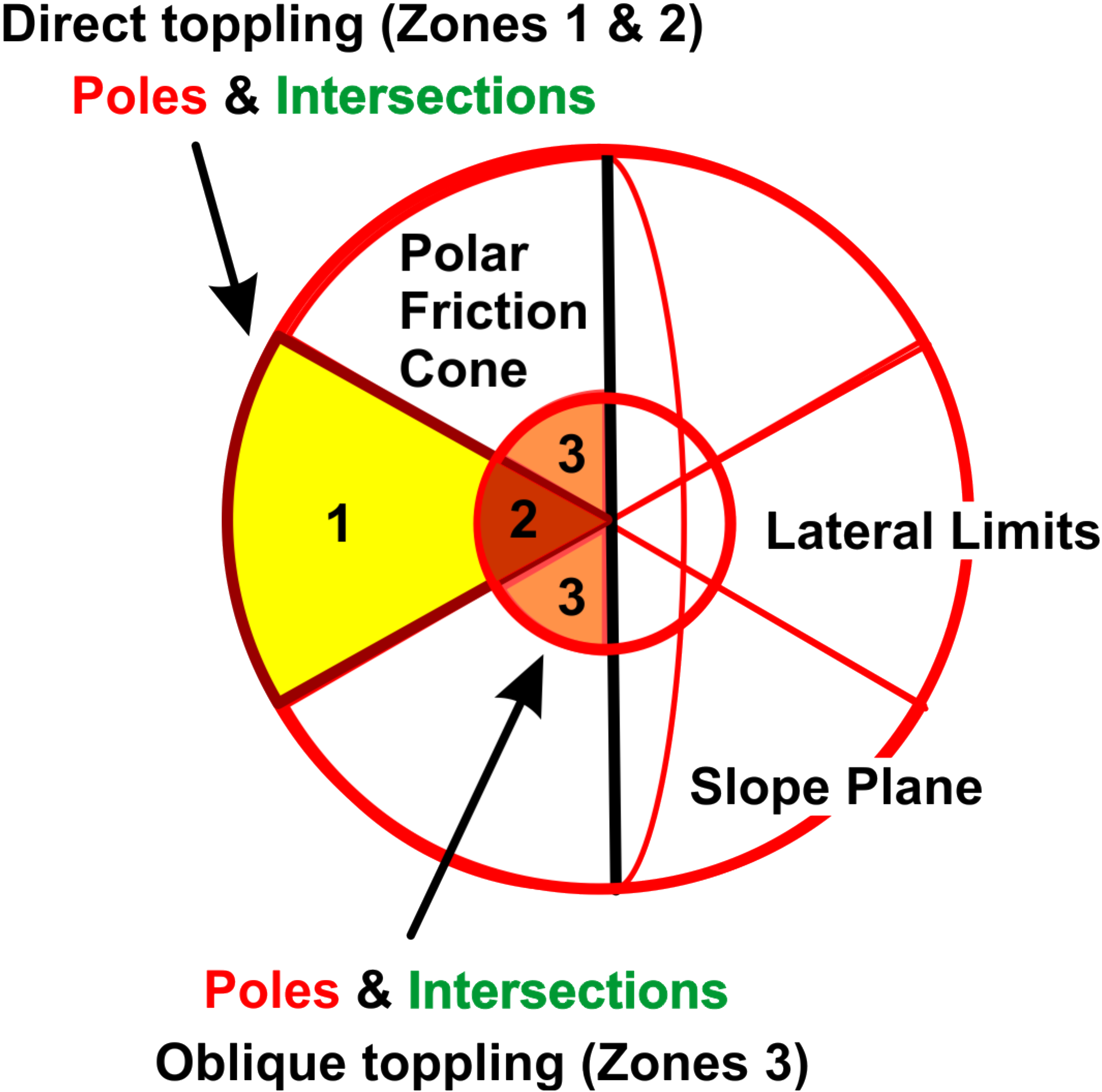
DIRECT TOPPLING
Breaking and toppling forwards of steeply slanting blocks or layers. OBLIQUE TOPPLING As intersections approach vertical, toppling to the sides outside the lateral limits, becomes more likely. |
|
| PROCEDURE | ||
|
|
Critical Intersections - Zones 1 and 2 Indicator for Direct Toppling in conjunction with critical poles of Base planes (see below). Critical Intersections - Zone 3 Indicator for Oblique Toppling in conjunction with critical poles of Base planes (see below). Critical Poles of Base Planes - Zone 2 and 3 Base planes inside the Polar Friction Cone and therefore will not slide but still may provide a release mechanism to blocks. Critical Poles of Base Planes - Zone 1 These Base planes can slip. Therefore, combined sliding and toppling modes may occur simultaneously.
|
|