Register Scans by Setting the Backbearing Alignment Angle
Via scanner internal compass
The From magnetic to true north offset
can be used if the scanner has an in built compass and GPS receiver. Entering
the location and altitude of the scanner adjusts the compass reading from
magnetic to true north. More accurate adjustment may be possible if localised
information is available to provide a further Offset
to local grid.
-
Highlight the scans to be registered in the project explorer.
-
On the Position and Filter ribbon tab navigate to the Register group. From the Register drop-down list select
 By Backbearing.
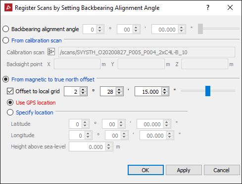
-
Select the From magnetic to true north offset option.
-
Choose Use GPS location to utilise the data collected from the scanner's inbuilt GPS receiver.
-
Enter the mean Height above sea-level (+/- 50 metres).
-
Click OK.
OR
Choose Specify Location and enter the latitude and longitude of the scanner location.
When using a vehicle mount.
If the vehicle mount was used in conjunction with the Maptek I-Site scanner, the backbearing alignment angle must be set.
The scanner is mounted on the roof of the vehicle and is referenced against two points; the scanner position and a reference point on the vehicle (second GPS point). The scanner is not physically backsighted to the reference point, but the relationship between the scanner orientation and the vehicle is fixed and can be measured from the scanned photograph. The reference point is very short compared with the scanner range, which will result in alignment errors that must be corrected.
The backbearing
alignment angle is the relationship between the scanner orientation and
the reference point. Once known, the same correction angle can be applied
to each scan acquired from that vehicle.
-
Load the scan into a view window.
-
Right-click on the scan and from the context menu and select Display panoramic data.
Note: If the scans do not have photographic data, right-click and select View scan from origin, pan to the area of interest and connect the scan.
-
Rotate the image until the reference point (second GPS point on the vehicle) can be seen.
-
On the Position and Filter ribbon tab navigate to the Register group. From the Register drop-down list select
By Backbearing.
Calculate the backbearing alignment angle
-
Load the scan into the Calibration scan field (drag and drop from the Explorer menu).
-
Click in the Backsight point X field and click on the reference point in the photograph. The tool will compute the angle between the scanner orientation and the reference point. This is displayed in the Backbearing alignment angle field.
-
Click OK to apply this angle to the calibration scan.
Apply the backbearing alignment angle
If the backbearing alignment angle is known, it can be manually entered.
-
Highlight the scan to be registered in the project explorer.
-
On the Position and Filter ribbon tab navigate to the Register group. From the Register drop-down list select
By Backbearing
option. -
Check the Backbearing alignment angle radial.
-
Enter the angle and click Apply.