Spherical Surface
Source file: spherical-surface.htm
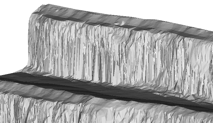
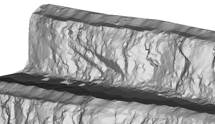
A spherical surface differs from a topographic surface, in that it is a 2D surface on a spherical grid instead of in the XY plane. This makes the spherical surface tool very useful for modelling overhanging surfaces.
Use this tool once scans have been registered and filtered using the tools on the Position and Filter ribbon tab.
-
Press P to put the scan in plan view.
-
Select the scan data in the project explorer.
-
On the Create ribbon tab, go to the Surface group and select
 Spherical Surface.
-
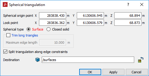
Enter coordinates or click in the view window to define the Spherical origin point. This is the centre point for the spherical grid.
-
Enter a value or click in the view window to select the Look point. This defines the radius of the spherical grid.
The origin and look point are displayed in the view window.
Note: If you are modelling only one scan, the spherical origin and look points are automatically set to the origin of the scan and backsight direction.
-
Rotate the view so that it is side on.
-
Alter the Z of the Spherical origin point so that the red arrow is perpendicular to the wall.
-
Select Surface or Closed solid from Spherical type according to requirements.
-
Select Trim long triangles eliminate long, incorrectly generated triangles. Enter Maximum edge length to define the maximum size of triangles being created.
-
Select Split surface along edge constraints to split the surface into separate objects, based on any lines or polygons selected in the project explorer when the surface is created. This option can be of use as a 'cookie cutter' when producing windows or a mine portal.
-
Click OK.
The surface is saved in the surfaces container by default.
Note: Once the surface has been created, it may require despiking. See Despike.


A topographic surface (left) and a spherical surface (right).
