Stereonet Contours
Source file: create-stereonet-contours.htm
Stereonet
contours ![]() help identify discontinuity sets. Contours represent density distributions of poles
and can be displayed as either wire-frames or flat shaded regions. You can
customise ranges of pole distribution and assign custom colours
to these ranges. Smoothing and Terzaghi weighting options are also available.
help identify discontinuity sets. Contours represent density distributions of poles
and can be displayed as either wire-frames or flat shaded regions. You can
customise ranges of pole distribution and assign custom colours
to these ranges. Smoothing and Terzaghi weighting options are also available.
With the stereonet ![]() in view, create contours as follows:
in view, create contours as follows:
-
On the Geotechnical tab, in the Stereonet group, click
 Stereonet contours.
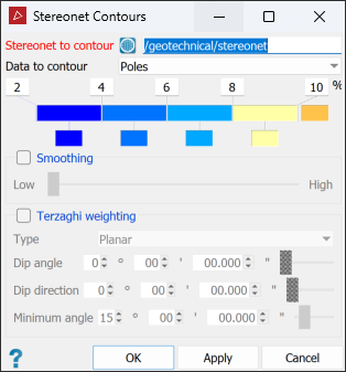
-
Drag the stereonet into the Stereonet to contour field.
-
From the Data to contour drop-down, select Poles or Intersections as the base objects for contours.
-
Adjust the colour scale as required. See Modifying a colour scale for detailed instructions.
-
Select Smoothing if required, and adjust the degree of smoothing.
-
Select Terzaghi weighting if desired.
Terzaghi weighting uses the measurement orientation to counteract sampling bias. You can apply weighting as either of the following types:
-
Select either Planar or Linear from the Type drop-down.
-
Planar gives bias to discontinuities less likely to intersect the specified plane.
-
Linear gives bias to discontinuities less likely to intersect the specified line.
-
Set the Dip angle and Dip direction (for planar type) or Plunge and Trend (for linear type).
TipFor planar type, create a discontinuity object of the whole slope face with the dip and strike
 Query tool, then drag the discontinuity object into the dip fields of the Stereonet Contours panel.
For linear type, create a discontinuity object of the linear feature, then drag the object into the plunge and trend fields of the Stereonet Contours panel.
-
Set the Minimum angle as the lowest angle between the measurement orientation and the discontinuity that may be used for weighting.
-
-
Click OK or Apply to generate contours.
The
contours are saved in the <stereonet name>
container.
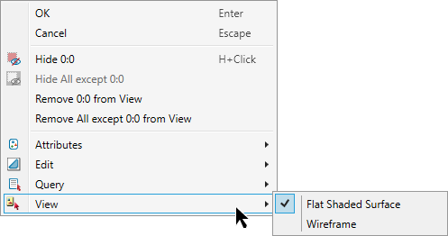
You can display contours as either wireframe or flat shaded.
-
To apply to the whole selection, on the Home tab, go to the Colour group. From the
 Appearance drop-down list select either Wireframe or Flat shaded.
 -
To apply to an individual contour, right-click on the object to open the context menu, go to
 View and select a surface appearance type to
change the contour display mode.
View and select a surface appearance type to
change the contour display mode.
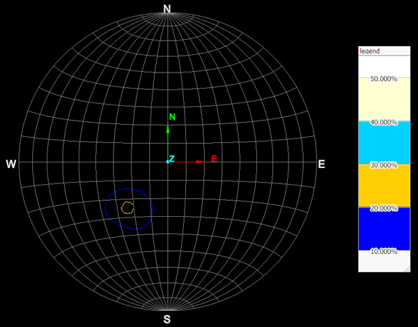
|
gap |
|
|
Stereonet contour (wireframe) and legend. |
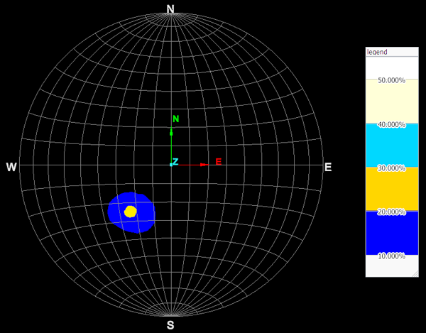
|
Stereonet contour (flat shaded surface) and legend. |
