Grade Control Optimiser
This tool generates optimal block classifications and polygon networks from a block model slice.
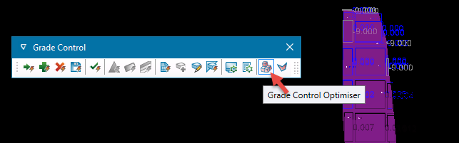
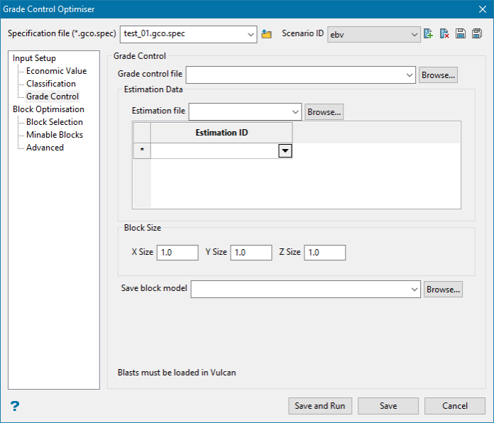
On the Block menu, click on Grade Control Optimiser to display the following interface.
You can also open the Grade Control Optimiser from the Grade Control toolbar.
Input Setup
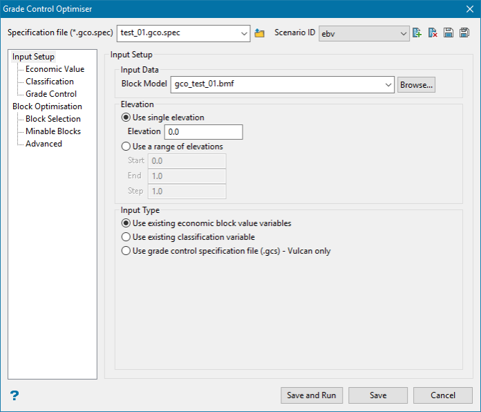
Specification file ( *.gco.spec )
Use the drop-down list to select the specification file if it is in the current working folder, or click the Browse icon to load a file from another location.
If this is a new project, enter the name for the new specification file.
Scenario ID
![]() New
New
![]() Delete
Delete
![]() Save as
Save as
![]() Save
Save
Resetting all values to the default state can be done in two ways:
-
Click the Scenario ID New icon
-
Click the Scenario ID Delete icon
This will reset all values in the Grade Control Optimiser GUI and reset all the values in the specification file. The only entry that will not be reset is the block model. However, the block model is not stored in the specification file.
Input Data
Block Model
Select the model that will be used as input.
Elevation
This is the elevation to reclassify. This must intersect the block model. Enter either a single elevation level, or use a range of elevations.
Input Type
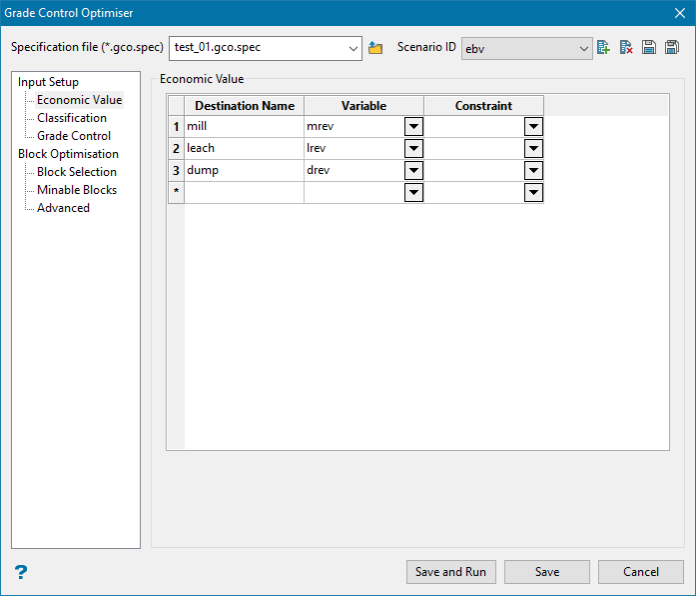
Grade Control Optimiser is designed to take economic information like pictured above, and multiple variables which indicate the economic information for each destination. However, it can also take a single variable with a prior classification.
Use existing economic block variables
This option is used when you want to provide a variable for each destination that contains the economic information. Like so:
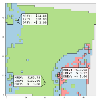
Three variables (mrev, lrev, drev) indicating the value for each classification.
The optimiser will reclassify blocks to satisfy the mining width constraint such that the overall values is maximized.
When this radio button is selected the Input Setup > Economic Value tab becomes active.
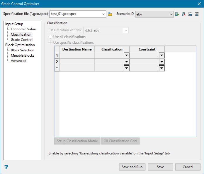
Use existing classification variable
This option is used when you do not have full economic information, and instead only have a single variable with a pre assigned classification (perhaps based on cutoffs). Like so:
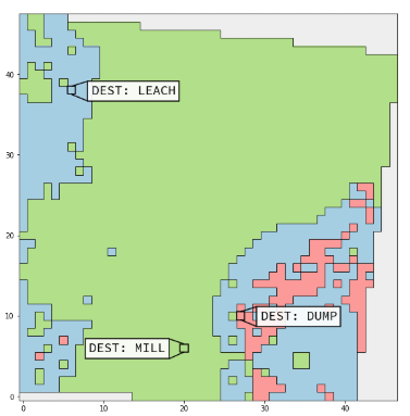
Single variable Dest with the initial classifications.
The optimiser will reclassify blocks to satisfy the mining width constraint such that the least number of blocks are changed. However, a custom classification matrix can be provided to refine this behaviour.
When this radio button is selected the Input Setup > Classification tab becomes active.
Use grade control specification file (.gcs) - Vulcan only
Use blasts loaded into Vulcan. Before running this option you will need to setup the calculation rules in Grade Control > Setup > Calculation Rules.
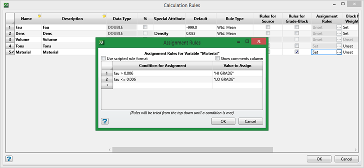
If the option Rules for Grade-Block has been selected, the rules will be applied to the resulting block model.
Note: If you select this option you will not be able to use the executable (gcopt.exe).
Economic Value
You must specify at least two destinations. Increasing the number of destinations vastly increases the running time of the operation.
Destination
The destination name, must be unique, will be saved into the output: Destination name on the Block Optimisation tab.
Variable
The variable in the block model specified on the Input Setup tab. This variable should be a double or float, and indicates the value the optimiser receives for sending the block to this particular destination.
Constraint
An optional constraint on this destination per block. A variable in the block model specified on the Input Setup tab. This variable should be an integer. Values of ‘0’ indicate that the block is not allowed to be assigned to this destination.
Be careful of indicating constraints that do not allow the mining width to be satisfied. If for example you constrain a single block to not be allowed anything other than destination 1, and then constrain all the blocks around it to be not destination 1 then this is an impossible problem.
Classification
Classification Variable
This is a variable in the Input Setup block model. This variable is the original classification for the problem, which will be modified to satisfy the mining width. It should be an integer or name type variable.
Use all classifications
This convenience selection means that the grid does not need to be filled out, and all of the classifications which are in the Classification Variable will be used. If it is an integer, the unique integers will be used, and if it is a name type variable the translation table names will be used.
Use specific classifications
When this is selected the grid must be filled out with at least two destinations.
Table values
Destination Name
The destination name, must be unique, will be saved into the output: Destination name on the Block Optimisation tab.
Classification
The value in the Classification Variable, with an integer classification variable this should be an integer, with a name type Classification Variable, this should be a value in the translation table.
Constraint
An optional constraint on this destination per block. A variable in the block model specified on the Input Setup tab. This variable should be an integer. Values of ‘0’ indicate that the block is not allowed to be assigned to this destination.
Important: Be careful of indicating constraints that do not allow the mining width to be satisfied. If for example you constrain a single block to not be allowed anything other than destination 1, and then constrain all the blocks around it to be not destination 1 then this is an impossible problem.
Note: If there are values in the Classification Variable that are not represented in the Specific Classifications grid, then they will be arbitrarily classified to something else in the classifications grid.
Setup Classification Matrix
The optimiser works by turning the classification input into an economic optimization problem. By Default it will create economic variables which have a value of ‘1.0’ if the block stays the same, and a value of ‘0.0’ if the block were to change to some other classification, different to the initial classification.
This default behaviour serves to minimize the number of blocks that are changed. However, there may be situations where the relative degree of value to changing blocks is different. That is, you may want to say that if a mill block is changed to a leach block, that is better than if it were changed to a dump block.
If this is the case you may Setup Classification Matrix and a popup will be shown:
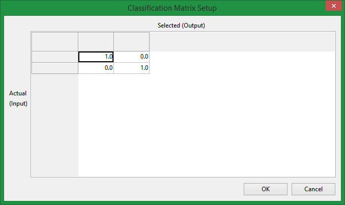
Read this matrix by column and then row. If a block is input as a specific destination in the Classification Variable then it will have a column, the rows in that column indicate the value for each possible output destination. That is, if a block is input as dest1, and the optimiser leaves it as dest1 it will receive one point. The optimiser would like to maximize points, so by changing the values you can change the relative benefit of a certain reclassification.
The values in the grid only matter relative to one another. They may be thought of as points that the optimiser gets for a certain change.
We suggest making only minor changes to this matrix while running the tool regularly to assess the effect of each change.
OK closes the sub panel saving the result into the scenario.
Cancel closes the sub panel discarding any changes.
Fill Classification Grid
This is a convenience button to read the block model, and block selection, then fill in any unique values into the grid.
Note: This will erase anything currently existing in the grid.
Grade Control
General workflow to create block model from grade control blasts
-
On the Grade Control menu, click Load specifications to load the grade control specification file.
-
Next, click Load Blast to load the blast that you want to use.
-
On the Block menu, click Grade Control Optimiser, then select Grade Control Optimiser.
-
Create a new specification file and a new Scenario ID.
-
Enter the elevation. This will be the centroid of the Z value of the block model.
-
Select Use grade control specification file (.gcs) –Vulcan only.
-
Go to Grade Control tab.
-
Select the grade control specification file.
-
Select the estimation file.
-
Select the ID’s that you want to run in the estimation.
-
Enter the block size of the block model.
-
Enter the name of the block model.
-
Go to the Block Optimisation tab and set the Destination ID.
-
Click the Save and Run button.
GCOPT will then generate the block model. The process will start and the block model will be created, estimated and the rules applied, and Grade Control Optimiser will run.
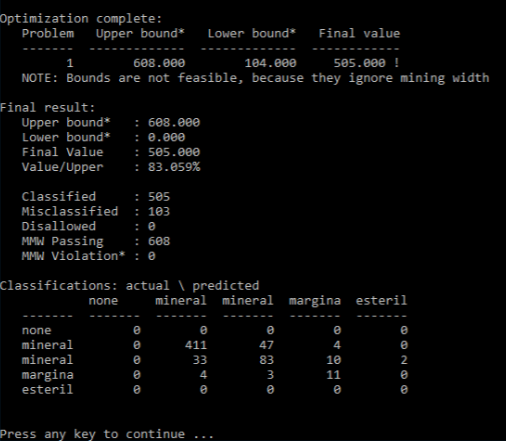
Then you can run Grade Control Polygons and get the results with the new block model created.
Block Optimisation
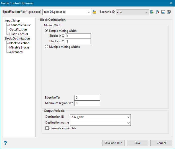
Mining Width
The mining width constraint is defined to the optimiser as a small collection of blocks, like a small template. The simplest option is to specify the mining width template as a rectangle. But it may also be preferable to provide a custom mining width, or even multiple possibilities.
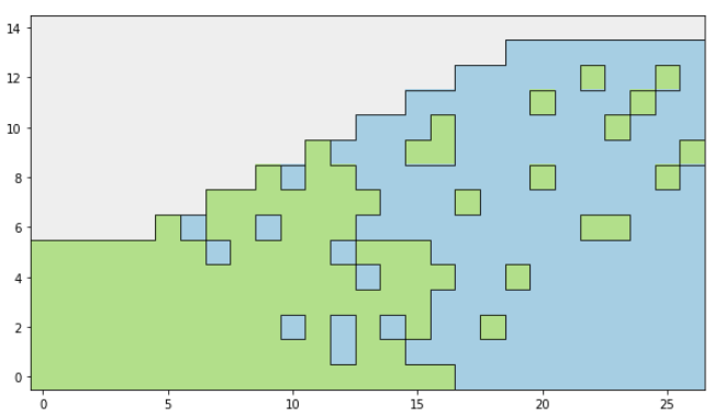
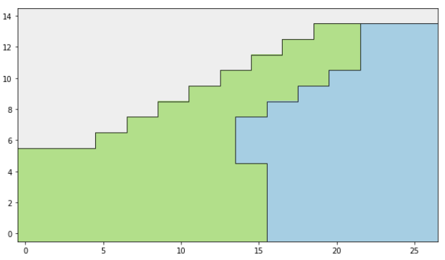
This is treated as a hard constraint. The blocks which are selected by the optimiser must satisfy the mining width. A block is said to satisfy the mining width when it belongs to a full template that has all of it’s blocks set to the same destination. So in the below image the dark blocks satisfy a 3x3 mining width.
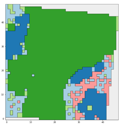
Baseline classification image, with darkened blocks passing a 3x3 mining width.
Simple Mining Width
A mining width as a rectangle.
Blocks in X
The number of blocks of the mining width rectangle in the X model direction.
Blocks in Y
The number of blocks of the mining width rectangle in th Y model direction.
Multiple mining widths
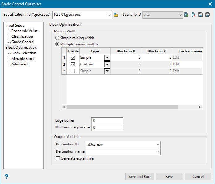
Multiple mining widths allows for the resulting pattern to consider more than just one single mining width, and also provides access to the custom mining width option, where the template is not just a simple rectangle.
A block is said to satisfy the overall mining width constraint if any one of the enabled multiple mining widths is satisfied.
When using multiple mining widths you should not include multiple mining widths where one of them could be constructed by the union of another elements translates. That is, you should not include both a 2x2 and a 4x4 because the 2x2 dominates the 4x4.
Enable
A convenience option to turn on and off different mining widths.
Type
Simple
Enables Blocks in X and Blocks in Y so this row will be a simple mining width rectangle.
Custom
Enabled Custom mining width so this row will be a custom mining width template defined on a grid.
Blocks in X
The number of blocks of the mining width rectangle in the X model direction.
Blocks in Y
The number of blocks of the mining width rectangle in th Y model direction.
Custom Mining Width
A more custom mining width defined on a small grid of checkboxes:
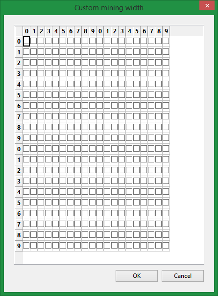
A grid to define the mining width element as you see fit.
When a checkbox is enabled it becomes a part of the mining width element. The checkboxes should form a single connected component, should not have any holes, and should tile nicely.
OK closes the grid and saves any changes.
Cancel closes the panel and discards any changes.
Note: It is very important that the element’s tile with one another, precisely because the mining width is treated as a hard constraint, and it may be impossible to tile certain shapes together.
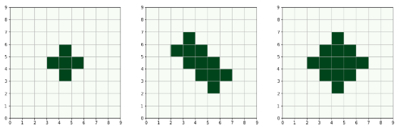
Some elements that work.
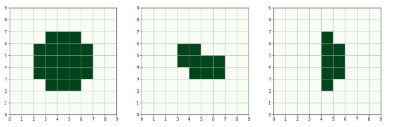
Some elements that do not work.
Edge Buffer
An integer, that controls a buffer around the outside of the model that allows the mining width constraint to be violated. A number of blocks. Typical values are between 0 and 4.
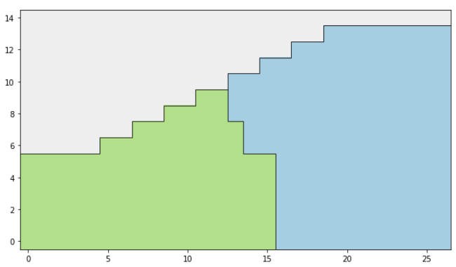
It may be absolutely necessary to allow an edge buffer in some circumstances, especially when considering a non-square optimization area. Consider the following example, with a 3x3 mining width.
We would like the blue blocks to remain blue, and the green blocks to remain green. So something like this would be a nice solution:
Unfortunately, that leaves two blocks that do not satisfy the mining width:
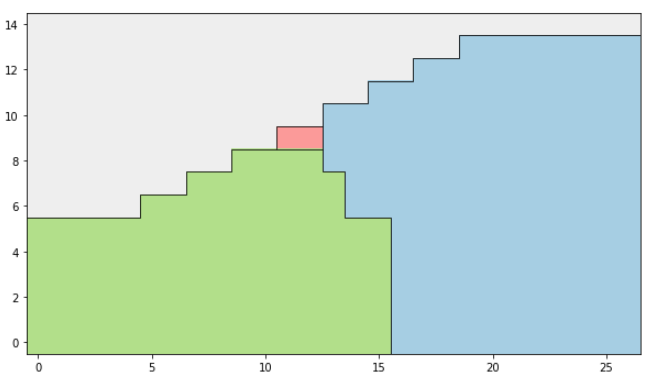
In order to change this we enter a cascading situation where we have two choices, both terrible:
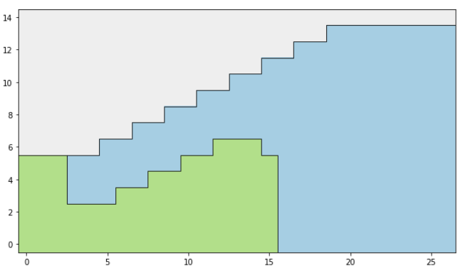
This is avoided by allowing an edge buffer even of just 1 block, which safely avoids this problem and allows this solution where the two blocks satisfy the mining width with the marked mining width element, that sits outside the allowed area.
Output
Destination ID
The destination ID is a integer variable in the input setup block model. It will be populated with the chosen destination with 1 for the destination in the first row, 2 for the destination in the second and so on. The rows are read from the appropriate grid (Either on the Economic Value or Classification tab).
Note: If the variable does not exist it will be created.
Destination name
The destination name is a name type variable in the input setup block model. It will be populated with the chosen destination’s Destination Name in the appropriate grid (Either on the Economic Value or Classification tab).
Generate Explain File
Optionally creates an explain file which contains extra information about the optimization process.
Block Selection
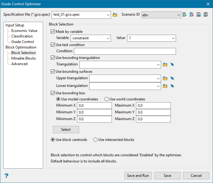
Mask by variable
Select the Mask by variable check box if you want to restrict the blocks by a block model variable. You will need to select the variable and value to mask by from the Variable and Value drop-down lists.
Example: To restrict blocks to those where Material equals Ore, select Material as the variable and Ore as the value. The block model variable may be alpha or numeric.
Use test condition
Select the Use test condition check box if you want to use a further constraint upon a numeric block model variable and enter the condition in the Condition field. The maximum size of the condition is 132 alphanumeric characters. (See the Vulcan 3D Editor > Core Appendixes > Appendix B topic for a full list of available operators and functions.)
Example: To select only blocks that have an iron value greater than 10.0, you would select the Use condition check box and enter Fe GT 10.0 in the Conditions field.
Use bounding triangulation
Select the Use bounding triangulation check box if you want to restrict the blocks by a triangulation. You will be required to specify the bounding triangulation. Select the triangulation to use from the Triangulation drop-down list, or click Browse to select a triangulation from a location other than your working directory.
Note: This option is not applicable to open or 2D triangulations.
Use bounding surface
Select the Use bounding surface check box if you want to restrict the blocks by bounding surfaces. If you select this option, you must select the Upper triangulation and Lower triangulation from the drop-down list, or click Browse to select a triangulation from a location other than your working directory.
Use bounding box
Select the Use bounding box check box if you want to restrict the blocks by a box. If you select this option, you must enter the minimum and maximum coordinates for X, Y, and Z in the Block model coordinates (X. Y, Z CENTRE) should be used section.
Minable Blocks
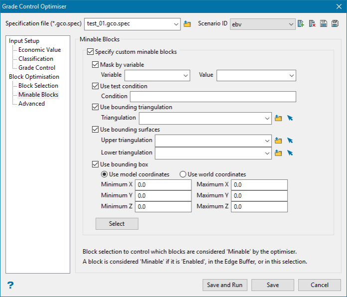
Specify custom minable blocks
Option to specify the minable blocks explicitly.
Minable blocks are where the mining width element may sit. They are controlled by the original block selection (any blocks that are chosen to be optimised are enabled, and therefore must be minable). Minable blocks are also controlled by the Edge Buffer. Above we have seen the importance of specifying appropriate minable blocks especially around edges.
This block selection allows the minable blocks to be more tightly controlled than with the broad brush that is the edge buffer.
Mask by variable
Select the Mask by variable check box if you want to restrict the blocks by a block model variable. You will need to select the variable and value to mask by from the Variable and Value drop-down lists.
Example: To restrict blocks to those where Material equals Ore, select Material as the variable and Ore as the value. The block model variable may be alpha or numeric.
Use test condition
Select the Use test condition check box if you want to use a further constraint upon a numeric block model variable and enter the condition in the Condition field. The maximum size of the condition is 132 alphanumeric characters. (See the Vulcan 3D Editor > Core Appendixes > Appendix B topic for a full list of available operators and functions.)
Example: For example, to select only blocks that have an iron value greater than 10.0, you would select the Use condition check box and enter Fe GT 10.0 in the Conditions field.
Use bounding triangulation
Select the Use bounding triangulation check box if you want to restrict the blocks by a triangulation. You will be required to specify the bounding triangulation. Select the triangulation to use from the Triangulation drop-down list, or click Browse to select a triangulation from a location other than your working directory.
Note: This option is not applicable to open or 2D triangulations.
Use bounding surface
Select the Use bounding surface check box if you want to restrict the blocks by bounding surfaces. If you select this option, you must select the Upper triangulation and Lower triangulation from the drop-down list, or click Browse to select a triangulation from a location other than your working directory.
Use bounding box
Select the Use bounding box check box if you want to restrict the blocks by a box. If you select this option, you must enter the minimum and maximum coordinates for X, Y, and Z in the Block model coordinates (X. Y, Z CENTRE) should be used section.
Advanced
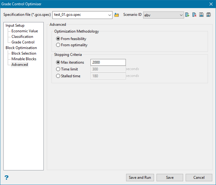
Optimization Methodology
Unfortunately, as with any sufficiently complicated problem, there are competing methods to solve the problem, that do not generally have a clearly better choice in all contexts.
In this problem, there are currently two main methods for epitomising which are named From feasibility and From optimality. Because one of the methods is not clearly better than the other in all scenarios, both are provided and you must choose.
Often you can run first one, with a minute time limit, and then the second, also with a minute time limit, and see in the results are substantially different. Some problems are well suited to each optimiser, so experimentation may be required.
From feasibility
The optimiser creates a very simple initial solution that satisfies the mining width and progressively tries to make it better, until the optimum is found.
Generally, From feasibility has faster iterations than From optimality, and tends to improve faster in the initial stages - however it can become bogged down and not make progress for a long time.
From optimality
The optimiser creates a simple initial solution that satisfies the mining width and also a solution that is optimal - but does not satisfy the mining width. It then progressively works backwards and forwards attempting to both improve the initial solution (while it still satisfies the mining width), but also to make the optimal solution satisfy the mining width. It does this until the optimum is found.
Generally, From optimality has slower iterations that From feasibility, and might improve a bit slower in the beginning. But often it will find the true optimum faster, and makes steady progress instead of slowing down.
Stopping criteria
Unfortunately some problems are simply too large to be solved to the optimum solution and the optimiser must be stopped. Regardless, the optimiser will always provide the best available solution if it is stopped. There are three methods of doing this:
Max iterations
The optimiser is stopped when the maximum number of iterations have been performed, or the optimum was found.
A special value of 0 may be specified in this box to prompt the optimiser to go until the optimum is found regardless of how long it takes (it is recommended to use From Optimality if this is desired).
Time limit
The optimiser is stopped when the time limit is reached, or the optimum was found.
Note: that the optimiser only checks the time after each iteration, so if the iteration is taking a very long time the time limit might be exceeded.
Stalled time
The optimiser is stopped if it has not found a better solution in the specified time, or if the optimum is found.

