Flag by Triangulations
Use this option to flag block models based on the location of each block centroid and a set of surface or solid triangulations.
Note: This option supports both standard and HARP models.
Instructions
On the Block menu, point to Manipulation, then click Triangulation Flag.
Follow these steps:
-
Select the specification file to flag from the drop-down list, or click Browse to select a file using the explorer.
-
Select the Scenario ID from the drop-down list. To create a new Scenario, enter a name in the field and click Save. To delete an ID, select the ID from the drop-down list, then click the Delete key on your keyboard.
-
Select the block model from the file drop-down list, or click Browse to select a file using the explorer.
-
Enable Create block model variables to create new block model variables automatically as the program is running. To create the new variables, type the name into the Variable column of the table.
-
Select the method of flagging. The inputs and setup are the same for each method.
-
Use block centroids - This method will flag the variable if the block centroid is within the boundaries of the triangulation.
-
Use block calculation script - Use this method if you are flagging a HARP model. This algorithm will create a block calculation script (.bcf) using the inputs of each row in the table, then use BCALC to flag the variables.
-
Use majority volume - Select this option to flag blocks by the triangulation that contains the majority of that block's volume, regardless of the centroid location.
Note: With this method you can only flag one variable at a time.
Select the variable that will hold the flag.
Note: When this is enabled, the option to select a variable in the table is automatically disabled.
Blocks that are intersected by more than one triangulation are flagged based upon which triangulation captures the largest proportion of volume within that block.

Figure 1 : In this example, the variable would be flagged as a C since it takes up the largest volume of the block.
Note: With this method you can also flag multiple variables.
Note: With this method you can also flag multiple variables.
-
-
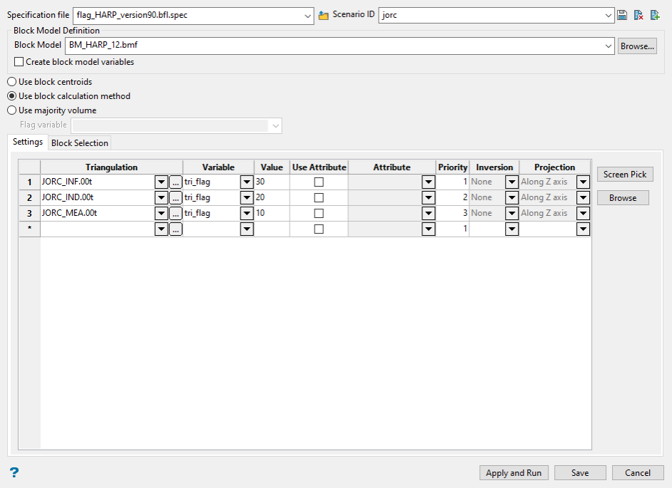
Use the Settings tab to identify how the block variables will be flagged.
-
Select a Triangulation. The drop-down list contains all triangulations in the current working directory.
-
Select a block model Variable in which to store the flagged values. You can select from the drop-down list which will show all valid variables already in the block model. You can also enter the name of a new variable if you have selected the option Create block model variables above.
-
Enter the Value to be stored in the variable when a block has been flagged.
-
Click Use Attribute to use the value stored in as a triangulation attribute as the flag value instead of the using what is in the Value column. Select an attribute from the drop-down list. All available attributes associated with the selected triangulation will be displayed in the list.
-
Use the Block Selection tab to identify which blocks will be used.
-
Specify the Priority for the order in which the triangulations will be recognised. This is only necessary if you are using more than one triangulation and they happen to be overlapping each other in certain areas. If you are only using one triangulation then the default value of 1 will be used. The higher the number, the higher the priority (a priority of 10 overrides a priority of 1).
-
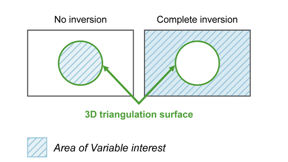
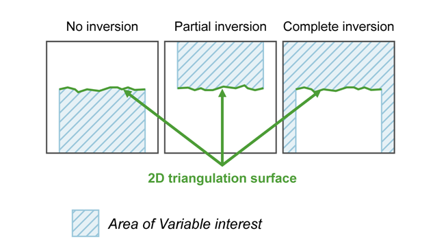
Specify the type of Inversion. Select None (no) inversion, Partial inversion, or Complete inversion. Partial inversion has not effect for 3D triangulations.
-
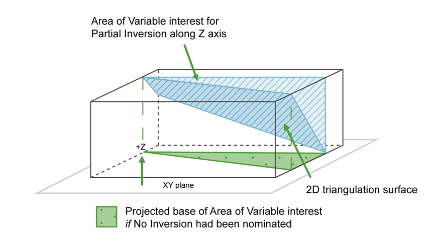
Select the Projection axis. The projection axis defines the direction for a surface and has no effect when working with solids. This option is used in situations where steeply dipping structures define regions.
-
Use the Block Selection tab to identify which block will be flagged.
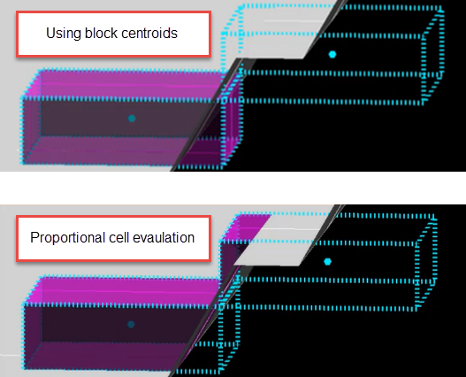
 Use block centroids or Proportional cell evaluation
Decide whether you want to use the entire block in the calculations or only the portion that is within the regional boundaries. By default, the evaluation method is set to Proportional cell evaluation; however, you can select between Proportional cell evaluation and Use block centroids. This is especially important when using options such as Bounding triangulation, Bounding box, Section thickness, or Bounding surfaces.
 Mask by variable
Select the Mask by variable check box if you want to restrict the blocks by a block model variable. You will need to select the variable and value to mask by from the Variable and Value drop-down lists.
Example: To restrict blocks to those where Material equals Ore, select Material as the variable and Ore as the value. The block model variable may be alpha or numeric.
Use test condition
Select the Use test condition check box if you want to use a further constraint upon a numeric block model variable and enter the condition in the Condition field. The maximum size of the condition is 132 alphanumeric characters. (See the Core Appendixes > B - Operators/Functions topic for a full list of available operators and functions.)
Example: To select only blocks that have an iron value greater than 10.0, you would select the Use condition check box and enter
Fe GT 10.0in the Conditions field.Use bounding triangulation
Select the Use bounding triangulation check box if you want to restrict the blocks by a triangulation. You will be required to specify the bounding triangulation. Select the triangulation to use from the Triangulation drop-down list, or click Browse to select a triangulation from a location other than your working directory.
This option is not applicable to open or 2D triangulations.
Use bounding surfaces
Select the Use bounding surface check box if you want to restrict the blocks by bounding surfaces. If you select this option, you must select the Upper triangulation and Lower triangulation from the drop-down list, or click Browse to select a triangulation from a location other than your working directory.
Use bounding box
Select the Use bounding box check box if you want to restrict the blocks by a box. If you select this option, you must enter the minimum and maximum coordinates for X, Y, and Z in the Block model coordinates (X. Y, Z CENTRE) should be used section.
Reverse selection
Select the Reverse selection check box if you want to exclude the selected blocks within the slice. If this check box is not selected, the entire block is included within the slice by default.
Note: The values must be valid for the variable type. For example, enter a number for numeric variables, or a string for name variables.
Tip: It is good practice to set priorities using sequences such as 10, 20, 30, etc., instead of using sequences such as 1, 2, 3, etc. This will allow you to insert additional triangulations at a later time without the need of resequencing the entire list.
Note: This is only available if you are using the Use block centroids method. It is not used when using either the Use block calculation script or Use majority volume methods.
Note: This is only available if you are using the Use block centroids method. It is not used when using either the Use block calculation script or Use majority volume methods.
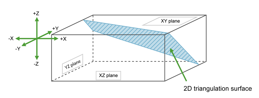
If No inversion is selected, the negative side of the triangulation is the area of interest. If Partial or Complete inversion is selected, then the positive side of the triangulation is the area of interest.
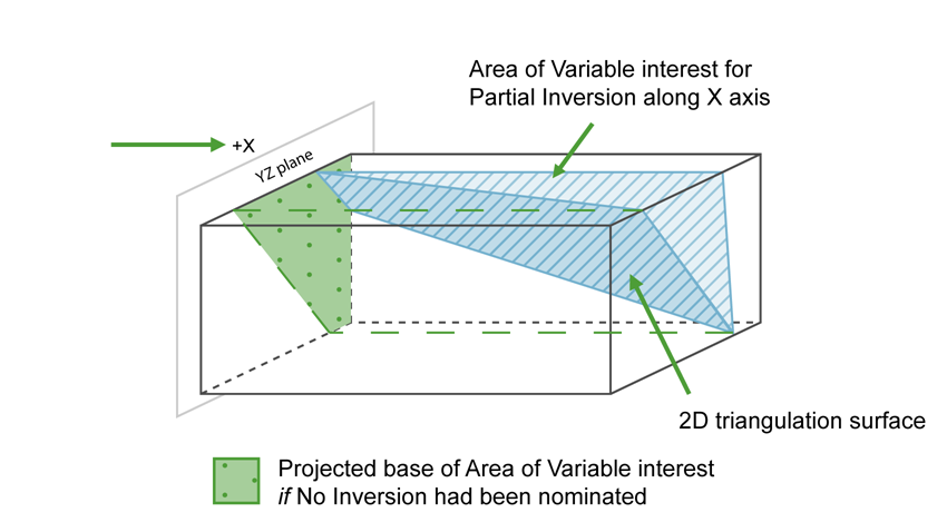
For triangulations (ore bodies) that are steeply dipping, it may be necessary to project along the X or Y axis to ensure the correct inversion is applies.
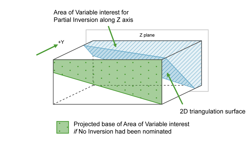
For triangulation (ore bodies) that are near to horizontal (lying in the XY plane), you would project along Z axis. The area of interest is then below the triangulation (if None (no inversion) is selected) or above (if Partial or Complete is selected).
Click Apply and Run to run the process and flag the triangulations.
Click Save to preserve all your settings.
Click Cancel to exit the panel without saving.

