Addition Parameters
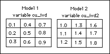
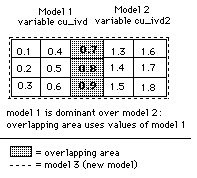
Use this option to perform operations on the values from the same variable in two different block models and see the results in a third block model. The two block models are combined according to the block size, offsets, and origin point specified for the resulting model in the block model definition file (.bdf). The two models may be overlapping each other totally, partially, or not at all.
Instructions
On the Block menu, point to Transfer, then click Addition Parameters.
Important: The block models must be indexed prior to using Block Model Addition. To index the block model, see Block > Manipulation > Index.
Specifications
![]()
Follow these steps:
-
Select the first block model from the drop-down list. The file name, including the (.bmf) file extension, can be up to 256 alphanumeric characters in length.
-
Select the second block model from the drop-down list.
Note: It does not matter which model you select as the first or second one. Only the variables are stored in the resulting (.bdf) file. The names of the block models are not stored.
-
Select the name of the new block model definition file (.adf) to be created from the drop-down list, or enter a name for a new one. The file name, including the file extension, can be up to 256 alphanumeric characters in length.
Note: The block model definition file name is taken from the new block model name. For example, if you enter FINAL as the new block model name, then your block model definition file will be named
<proj>FINAL.adf.
-
The option Prioritize speed over memory usage is enabled by default. However, you may disable this feature if you want to do so. On older computers or when manipulating very large models it may be beneficial to disable this option.
Output Schema
![]()
The final model constraints (block extents and block size) are controlled by a schema.
Follow these steps:
Schema Selection
-
Select a schema.
Note: The first and second model parent schemas must be multiples of each other. The final model's parent schema must encompass both other parent schemas.
-
Parent schema from <model_1> - Select this option to use the parent schema of the first block model.
-
Parent schema from <model_2> - Select this option to use the parent schema of the second block model.
-
Combined Parent schemas - Select this option to use the parent schemas of both models. The schema will encompass the model one and two schemas.
-
-
Enter the Offset min/max distances required to define the 3D extent of the model. The distances are relative to the origin.
-
Enter the Origin. The origin defines the start of the offsets in the schema and the pivot for rotations.
-
Enter the maximum Block size for the X, Y, and Z directions.
The schema for the new (combined) model is then calculated. Sub-blocks are created based on the minimum number of cells required to represent the geometry of the new block model from the smallest cells available. See the Schemas option (under the Construction submenu) for more information on sub-blocking.
-
Click the View Extents button to show the extents of the input and output models on the screen.
Variables
![]()
Follow these steps:
Select how you want to populate the table.
-
Click Populate to automatically populate the table with the variable names and data from both block models.
-
Click Populate From First Only to automatically populate the table with the variable names and data from the first block model listed.
-
Click Populate From Second Only to automatically populate the table with the variable names and data from the second block model listed.
Tip: You can also use this table to add variables in addition to the variables of the two block models.
There are two reasons for allocating variables to the new model. One is a measure and the other shows type.
1. The variable may represent some measurement such as a grade estimation for that volume.
2. The other is that the variable may represent a boundary, for example, one side of a surface or inside a certain geological zone, or ore and waste.
Note: The number of variables in the new model cannot exceed 300.
| Table Columns | |
|---|---|
|
Resultant Variable |
Use this column to enter a variable name for the block model that will be created by the addition of the other two. The variable name, which can contain a maximum of 30 alphanumeric characters, must start with a letter. Block model variables that will be used for export to Isis databases should not have a name exceeding 5 alphanumeric characters. |
|
Variable Description |
Enter an optional 40 alphanumeric character description of the variable. |
|
Create Variable |
For each variable that you want to include in the new model, check the Create variable check box. |
|
Default value |
Enter the default value. The following characters may be used in combination with the default value, but not on their own:
Note: We recommend that the default value is not a true value, that is, the default value does not occur in the block model. The reason for this is that in reserves reporting, default values are reported as an "unknown" category. For example, if you assign 2.8 as the default value for SG, and 2.8 happens to also be the global block SG value, then the reserves calculation will report the "true" 2.8 values in the wrong category (the "unknown" category). It is therefore better to use a non true default value such as -99 and then run a script to re-assign all blocks to 2.8. This way the blocks with SG = 2.8 will be reported in their correct category. Important: Byte and short data types must not have a negative default value because they are unassigned. |
|
Data Type |
Note: Variables to be used as the estimated grade in grade estimation must be of a float or double data type. |
|
Generate Output Value Method |
The following options relate to how the variables are to be merged. Only one method can be chosen.
|
|
First Model Input Variable |
Select the input variable from the first of the two block models used to perform the addition. |
|
Second Model Input Variable |
Select the input variable from the second of the two block models used to perform the addition. |
|
Mapped Variable |
Note: This option is available only if you have selected Direct Mapping in the Generate Output Value Method column. After clicking the |
|
Use Scripting File |
Note: This option is available only if you have selected Use Scripting File in the Generate Output Value Method column. After clicking the |
 button, use the drop-down list to select the dominance order of the variables. In the list, the block model name precedes the variable name.
 button, use the drop-down list to select a script file. The list will only contain <proj><var>.bcf and <proj><name>.bcf script files. Click Browse to select a file from another location.
Buttons
Create ADF - Click to generate a block definition file (.adf).
Run Addition - Click to generate a block definition file (.adf), and run the addition program.
Cancel - Click to exit the panel without saving any of your changes.

