Archive
Use this option to save a layer to an archive file. The resulting file can be imported back in as a block model by using the Load Archive function.
Instructions
On the Block menu, point to Transfer, and then click Archive.

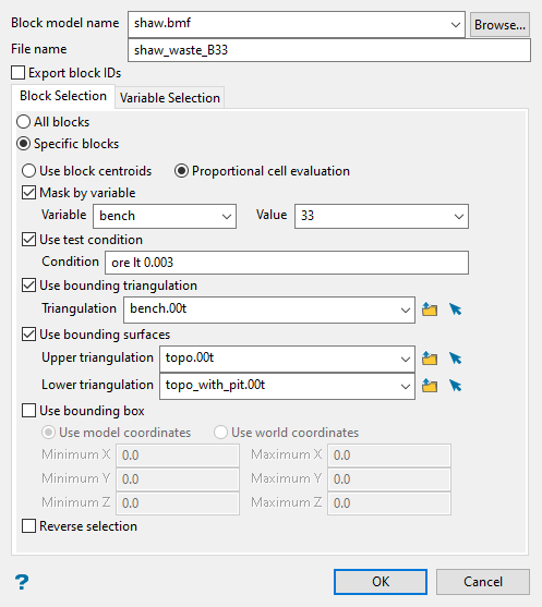
This panel is divided into two tabs, a Block Selection tab and a Variable Selection tab.
Block Selection allows you to determine which blocks of the model to use. Here you can use various options to limit the blocks that are archived, such as by variable, triangulation, or condition.
Variable Selection allows you to select the variables from your block model that will be saved to the archive file.
Follow these steps:
-
Begin by selecting the block model from the Block model name drop-down list. All block models that are located in your current working directory will be listed. If you want to use a block model that is stored somewhere else, click the Browse button and navigate to the correct file location.
-
Enter a name for the archive file in the space labelled File name. You do not need to include a file extension. The file will be saved with the extension (.archive_b) automatically, which can then be used with the option Load Archive to create a new block model.
-
Select the option Export block IDs if you want to export the index ID number for each block. This may be useful if you wanted to do a block model comparison between the original model and a new one created from the archive file.
NoteBlock IDs are not guaranteed to be preserved when you make a similar model. They are almost guaranteed to be different when exporting with Block Selection, so if you would like to keep a record of the block ID in the new model, you could put them in a variable.
Not many people or options use block IDs, but
DJBMEST.EXE, for example does.
Figure 1 : In the Explain options above, n1, n2, n3 are block IDs.
-
By default, Select all blocks will be automatically selected. However, if you want to limit which blocks are used, enable the option Specific blocks. This will make all the other options on the Block Selection tab available.
-
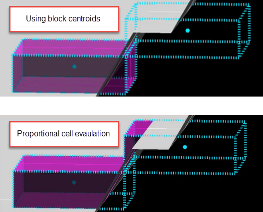
Next, decide whether you want to use the entire block or only the portion that is within the regional boundaries. By default, it is set to Proportional cell evaluation, however, you can select between Proportional cell evaluation and Use block centroids. This is especially important when using options such as bounding triangulations, bounding box, or bounding surfaces.

-
Set the criteria for which blocks will be used by selecting one or more of the following options:
Important: Block selection is cumulative. Therefore, all arguments defined on this panel must be satisfied for a block to be included.
Mask by Variable
This works well for variables holding alpha values. You will need to specify the variable, as well as a particular value.
Example: If you have a variable called Material in your block model and want to restrict blocks to those where Material equals Ore, select
materialas the variable and enteroreas the value.Use test condition
This works well for numeric variables. Enter a condition that must be true for the selected variable.
Example: To select blocks where iron has a value greater than 10.0, the condition would be
Fe GT 10.0The maximum size of the condition is 256 alphanumeric characters. Refer to Appendix B of the Core Appendices for a full list of available operators and functions.
Use Bounding triangulation
This option is useful when you want to restrict the selected blocks to a particular solid triangulation, such as a stope or bench solid.
Select a triangulation solid from the drop-down list, or click the small folder icon to select a solid that is stored in a subfolder. You can pick a loaded triangulation from the screen by clicking the small arrow icon.
Use bounding surfaces
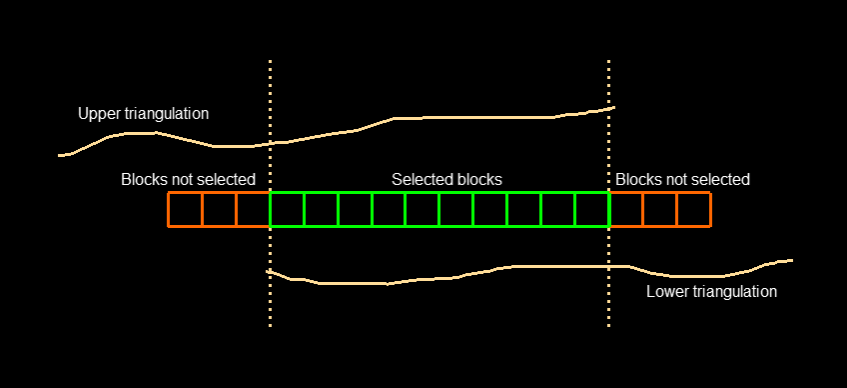
To restrict blocks to those that lie between two bounding surfaces, use the drop-down lists to select an Upper triangulation and a Lower triangulation. Use the small folder icon to select a solid that is stored in a subfolder. You can pick a loaded triangulation from the screen by clicking the small arrow icon.
NoteOnly blocks that lie in the overlapping sections of the surfaces, as viewed in plan view, are selected.

Figure 2 : Only the green blocks in the centre that are located between both the upper and lower triangulations will be selected.
Use Bounding box.
There are two choices for setting up a bounding box, Use model coordinates and Use world coordinates.
Use model coordinates
This method creates a box based on the offset distance from the block model origin.
If you had a block model that was 2000 x 2000 x 500, and you wanted to limit the blocks to a region that was 500 x 500 x 200 near the centre of the block model, the coordinates would be:
Minimum X 750 Maximum X 1250 Minimum Y 750 Maximum Y 1250 Minimum Z 150 Maximum Z 350 Use world coordinates
This method creates a box based on real-world coordinates instead of using offsets.
If you had a block model that was 2000 x 2000 x 500 with an origin located at (65,450.00, 4900.0, 4500.0), and you wanted to limit the blocks to a region that was 500 x 500 x 200 near the centre of the block model, you would need to enter the
Minimum X 66,200 Maximum X 66,700 Minimum Y 5,650 Maximum Y 6,150 Minimum Z 4,650 Maximum Z 4,850 Reverse selection
Select this option if you want to pick all the blocks that do not meet the criteria for any of the other selection methods you have set up.
Example: If you selected a bounding triangulation called
ore_shape.00t, then reversing the selection would cause all the block outside ofore_shape.00tto be selected instead of all the blocks inside of that shape.
-
Click OK.

