Image Slice
Use this option to create an image of a slice through a Vulcan block model. The resulting slice is saved as an (.ireg) file, which can then be attached to a triangulation.
Instructions
On the Block menu, point to Viewing, and then click Image Slice.
Note: If a block model is not currently open, you will be prompted to open one first.

Follow these steps:
-
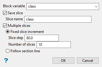
Select a variable using the Variable name drop-down list.
-
Click Save slice to setup your saving options.
Select this check box to save the resulting slice(s). The slice name, including the (
.bsf) file extension, can contain up to 20 alphanumeric characters in length (spaces are not allowed). The resulting file will be stored in your current working directory.If you create multiple slices, then a incremental number will be attached to the name.
Example: Using the slice name
classshown in the screenshot above, if 10 slices are created then the names of each slice will beclass1, class2, class3, ... class10.
-
Select the Multiple slices option to create more than one slice.
-
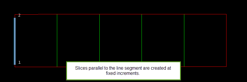
Fixed slice increment - Select this option to create the slices at a fixes increment. You will need to specify the number of slices to create, as well as the slice step.

-
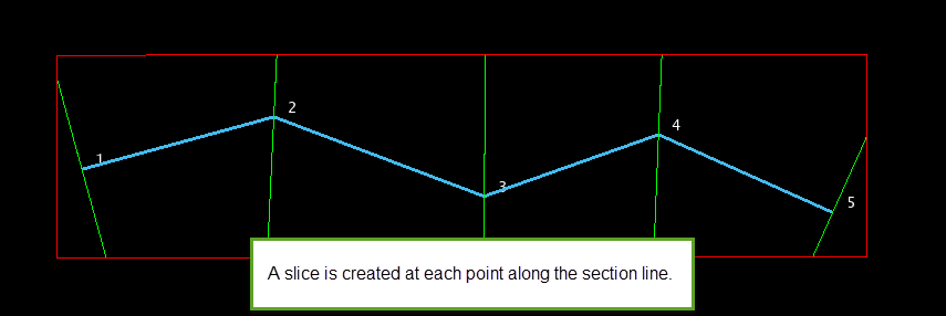
Follow section line - Select this option to create the slices using an existing section line. Once the Block Model Slice panel is complete, you will be required to select the section line from the screen. A slice will be generated at each point along the chosen line.

-
-
Click OK. You will then be asked to select the colour legend you want to use.
You will then be asked to select the colour legend you want to use.
-
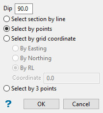
Define the orientation of the image slice(s).
Note: If you are creating multiple slices, and have chosen to use an existing section line (the Follow section line option from the Block Model Slice panel), then you will be prompted to select the section line instead.

-
Dip - This is the angle of the section from horizontal. Valid dip angles are between -90° and 90°.
-
Select section by line - Select this option to define the plane by selecting an existing line and specifying the dip.
Only design strings may be picked and it is not possible to pick a line in an underlay. The direction of the view, and therefore the direction of the stepping, depends on the digitised sequence of the line. The digitised sequence of the line can be reversed using the Reverse option (under the Design > Object Edit submenu).
-
Select by points - Select this option to define the plane by digitising two points and specifying the dip.
To locate a point precisely, use the Snap to Objects
 or Snap to Points
  modes on the Digitise toolbar. Points may be snapped onto underlays, such as block model slices or triangulations. If you use Indicate
  mode to select the points, then the points have the current default Z value.
 -
Select by grid coordinate - Select this option to define the plane by using a specific grid coordinate. The grid coordinates can contain up to three decimal places. To achieve the best results for the following three methods, we recommend using the Zoom Data Extents button
 on the Graphics toolbar in order to view all of the graphics.
-
By Easting - Select this option to enter a specific Easting value (X value).
-
By Northing - Select this option to enter a specific Northing value (Y value).
-
By RL - Select this option to enter a specific elevation value (Z value).
-
-
Select by 3 points - Select this option to define the plane by digitising 3 points.
Note: To locate a point precisely, use the Snap to Objects
 or Snap to Points
  modes on the Digitise toolbar. Points may be snapped onto underlays, such as block model slices or triangulations.
Using this option will allow you to explicitly define the location and orientation of a plane by indicating 3 points. The first two points define the bearing of the plane, and the third point defines the dip of the plane.
-
-
Click OK.
The slices are then created.

