Register
Register an Object onto a Surface
Use the Register option to register an object onto a grid mesh or triangulated surface.
This option can also be accessed by selecting the Register button ![]() from the Move toolbar.
from the Move toolbar.
Note: The required surface triangulation or grid mesh must already be loaded prior to using this option.
Instructions
On the Design menu, point to Object Edit, and then click Register.
Select the model onto which you want to register your object. If only one model is loaded, then you will not be prompted to select the model.
The Multiple Selection box is then displayed. Use the Multiple Selection box to choose the method of selecting objects and then select the objects.
The panels that appear after the objects have been selected depend on whether the surface is a triangulation or grid mesh.
Triangulation
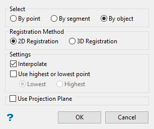
If the surface is a triangulation, then the String Registration panel displays.
The objects (strings) can be registered as either 3D or 2D. Generally, 2D registration is used for surface triangulations and 3D registration for solid triangulations. Take care with 3D registration as the strings to be registered should be close to the triangulation to obtain reasonable results. Digitising the original object by snapping onto the triangulation will give the best results.
Care must also be taken near sharp corners in a solid triangulation. Problems can occur when a corner is greater or equal to 90 degrees. In such cases unexpected (and strange) registering may occur. To avoid these problems, the original string should have a point snapped onto the sharp corner (i.e. the string doesn't pass above or through the corner). For example, in the case of a cube, the string to be registered should have points snapped to the edges of the cube (in the case where the registered string must go from one face to another).
If the Use highest or lowest point check box is not checked, then the string will be draped across the surface, that is, the Z values of points in the string will correspond with the Z values of the surface that the string is being registered with.
Define Plane
Applicable only to 2D registration
Select this option to define a plane for the registering. If this option is not selected, then the XY plane is used. This means that the object's Z coordinates are altered such that it is draped on top of the model.
You can use this option to define a different plane. An easy way to define the plane is to align the view with the plane that you want to use and then select the Three Point option and use Indicate mode ![]() to digitise the three points.
to digitise the three points.
The Register plane panel displays once the current panel has been completed.
Specify the triangles that you wish to delete. If you ticked the Use projection plane checkbox, then the Projection Plane panel will be displayed first.
-
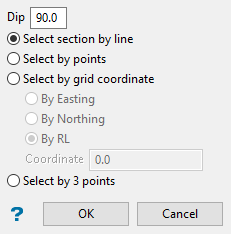
Dip - The dip is the angle of the section from horizontal. Valid dip angles are between -90° and 90°.
-
Select section by line - Select this option to define the plane by selecting an existing line and specifying the dip. Only design strings may be picked and it is not possible to pick a line in an underlay. The direction of the view, and therefore the direction of the stepping, depends on the digitised sequence of the line. The digitised sequence of the line can be reversed using the Reverse option (under the Design > Object Edit submenu).
-
Select by points - Select this option to define the plane by digitising two points and specifying the dip.
Note: To locate a point precisely, use the Snap to Objects or Snap to Points modes (on the Digitise toolbar). Points may be snapped onto underlays, such as block model slices or triangulations. If you use Indicate mode to select the points, then the points have the current default Z value.
-
Select by grid coordinate - Select this option to define the plane by using a specific grid co-ordinate. The grid co-ordinates can contain up to three decimal places.
Note: To achieve the best results for the following three methods, we recommend using the Zoom Data Extents icon (on the Graphics toolbar) in order to view all of the graphics.
-
By Easting - Select this option to enter a specific Easting value (X value).
-
By Northing - Select this option to enter a specific Northing value (Y value).
-
By RL - Select this option to enter a specific RL value (Z value).
-
Select by 3 points - Select this option to define the plane by digitising 3 points. To locate a point precisely, use the Snap to Objects or Snap to Points modes (on the Digitise toolbar). Points may be snapped onto underlays, such as block model slices or triangulations.
Note: Using this option will allow you to explicitly define the location and orientation of a plane by indicating 3 points. The first two points define the bearing of the plane, and the third point defines the dip of the plane.
Select OK.
Interpolate
Applicable to both 2D and 3D registration.
Select this option to insert extra points where needed. Points will be inserted where the registered string crosses a triangle edge or vertex.
In the case of a 2D registration, the W field will be linearly interpolated from the two neighbouring points in the original string. In the case of a 3D registration, the W field will be set to the preceding original data point.
The Name field will always be set to the Name of the preceding original data point.
Lowest Point
Select this option to register an object to the lowest point on a triangulation. Alternatively, the highest point can be selected.
Highest Point
Select this option to register an object to the highest point on a triangulation. Alternatively, the lowest point can be selected.
Click OK.
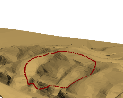
The objects are then registered onto the surface and you are asked whether or not you want to keep the registration. The Rotation tools on the Graphics toolbar can be used to check whether an object is registered.
Grid Mesh
If the surface is a grid mesh, then you are asked whether or not to interpolate points.
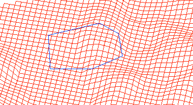
Interpolate inserts extra points into the objects (where needed), using interpolated X, Y and Z coordinates. Existing points will have their Z values interpolated to correspond to the model. In this way, the objects will be registered onto the model with greater detail and accuracy. Do Not Interpolate does not insert extra points into the objects. Existing points will still have their Z values interpolated to correspond to the model.
Once a selection has been made, the objects are registered onto the surface and you are asked whether or not to keep the registration (as for triangulations). The Rotation tools can be used to check whether an object is registered.
Tip: Preselected design data can be used with this option, that is, objects are selected prior to running the Register option. Using preselected data will allow you to bypass the Multiple Selection box.

