Export Block Model Data to PDF
Use the Export Data to PDF option to export block models, design data, and triangulations to a three dimensional PDF file. Once exported, the resulting file can then be viewed with any application that supports PDF viewing, such as Adobe Acrobat. Additionally, using a VRML plug-in, you can insert the file into a variety of applications such as Microsoft Word or PowerPoint, or into a website.
If you are working with data to be selected from the screen, load the desired entries before accessing the Export submenu.
Note: If a line has multiple colours, the resulting PDF file will have a component for each colour on that line.
Instructions
On the File menu, click Export to display the Export panel.
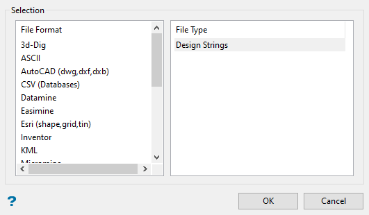
Click PDF in the File Format column on the left.
Select Block Models/Design Strings/Triangulations from the File Type field on the right side of the panel.
Click OK to display the Export to PDF panel.
Block model attributes
Block model file name
Enter or select from the drop-down list, the name of the loaded block model. Click Browse to select a file from another location.
Output name (.pil)
Enter, or select from the drop-down list, the name of the pit list file (.pil) that will be created from the export function. This file will store the block model information. If a block model is not currently open, you will be prompted to open one first.
Variable name
Enter, or select from the drop-down list, the name of the variable you want to export.
Colour scheme
Select the colour legend to be used to colour the chosen grade variable. The drop-down list contains all block colour legends found within your colour scheme file (.scd).
Block selection
Block Selection
Either all blocks or specific blocks can be selected. If you select Select specific blocks by, then you must enter one or more of the following selection criteria:
Variable
Select this check box to restrict the blocks by a block model variable. You will need to specify the variable as well as a particular value.
For example, to restrict blocks to those where Material equals Ore, select Material as the variable (from the drop-down list) and enter Ore as the value. However, if you require all blocks that do not have this specified value, then enable the Reverse matching check box. The block model variable may be numeric (for example the grade variable Au) or character (for example Geology) variables.
Bounding triangulation
Select this check box to restrict the blocks by a triangulation. This is useful when you want to evaluate reserves within a particular solid triangulation such as a stope.
To select blocks outside of the bounding triangulation, select the Select blocks outside the solid only option.
You may also select the Use proportional block evaluation check box and use it with this restriction.
Note: This option is not applicable to open or 2D triangulations.
Bounding box
Select this check box to restrict the blocks by a box. The bounding box is defined in Interactive or Coordinate mode. The required mode is selected from the Box Thickness panel, which is displayed once the Block Selection panel has been completed. You may also select the Use block centres check box and use it with this restriction.
Include planed blocks
Select this check box to restrict the blocks by a section plane. You will need to enter its associated thickness. The blocks that are within this thickness will be selected.
The section plane can be selected by line, points, or grid coordinates. This information is entered through the Section Plane panel, which is displayed once the Block Selection panel has been completed.
You may also select the Use proportional block evaluation check box and use it with this restriction.
Condition
Select this check box to use a further constraint upon a numeric block model variable, for example Fe GT 10.0 (iron value greater than 10.0). The maximum size of the condition is 132 alphanumeric characters. A list of available operators/functions to use when defining this condition is provided in Appendix D.
Bounding surfaces
Select this check box to restrict the blocks by bounding surfaces. Once the Block Selection panel has been completed, you will be required to select the top and bottom surface triangulations on the screen. Only blocks that lie within the overlapping sections, as viewed in plan view, of the surfaces are selected.
You may also select the Use proportional block evaluation check box and use it with this restriction.
This check box will be disabled when the Cut and fill surfaces check box is in use.
Single bounding surface
Select this check box if you want to restrict the blocks by a single bounding surface. Select the Project down z axis check box if you want to project down the Z-axis, that is select the blocks that fall below the nominated surface. If this check box is not selected, then all blocks that fall above the nominated surface will be selected instead.
Use proportional block evaluation
Select this check box if you want to use the full cell evaluation method. If this check box is not selected, then the proportional cell evaluation method will be used instead.
-
Full cell evaluation: Include blocks if the block centroid is within the region. The entire block will be included.
-
Proportional cell evaluation: Include those blocks that touch the region, and evaluate reserves according to the proportion of the block's volume that lies within the region. Proportional cell evaluation calculates and reports the exact proportion of a block within a solid triangulation. When selecting blocks, all blocks that touch the region are selected.
Click OK.
The blocks are then exported. The progress and any errors displays in a shell window.
Related topics

