Bench Plans
Create Slices and Generate Mine Reserves
Use the Bench Plans option to create automatically slices through an area containing a block model, pit design or contours and generate mine reserves.
Note: Before using this option you must have loaded a pit triangulation or strings to create a pit, a surface triangulation and an object to use as a grid plus have a block model open.
Instructions
On the Geology menu, point to Drilling, and then click Bench Plans to display the Zone Plans panel.
Zone plan layer name
Enter the prefix of the layer in which to store a single bench. The actual layer is called <zone_plan_layer><RL>. The maximum size of the prefix is 5 alphanumeric characters.
Bottom bench RL
Enter the Z value of the start bench plan.
Top bench RL
Enter the Z value of the end bench plan.
Bench height
Enter the bench height.
Use long term mining increment layers
Select this check box to use mining increment layers.
Use toe and crest of final pit design
Select this check box to generate toe and crest strings of a loaded triangulation of a pit. Upon completion of this panel the Toe and Crest of Pit panel displays.
Use block slices from a block model
Select this check box to generate block model slices (block model must be open). Upon completion of this panel the Block Model Slices panel displays.
Use contours through block model
Select this check box to generate block model contours (block model must be open). Upon completion of this panel the Block Model Contours panel displays.
Use ground contours outside pit limit
Select this check box to generate contours (triangulation must be loaded). Upon completion of this panel the Natural Ground Contours panel displays.
Use mid bench contours of triangulations
Select this check box to generate contours of triangulations at the mid point of each bench. Upon completion of the panel the Mid Bench Contours panel displays.
Calculate mining reserves
Select this check box to generate reserves in the bench plan. Upon completion of this panel the Calculate Reserves panel displays.
Note: The grade variables used in the calculation of the reserves are Fe, Sio2, al203 p, density variable is density. The variables must be in the block model. The calculation of the reserves uses a cut-off level of "-99".
Click OK.
If none of the options on the Zone Plans panel have been checked, or only the Use long term mining increment layers, then you will be prompted as to whether or not to generate the zone plans.
If any of the other check boxes on the Zone Plans panel have been enabled, then the confirmation box will not appear until the appropriate panels for the selected options have been completed.
Toe and Crest of Pit panel
The Toe and Crest of Pit panel displays when the Use toe and crest of final pit design check box has been checked.
You can use either the existing triangulation or build a new one. If you select to build a new one, then the Triangulation panel displays upon completion of the current panel.
Refer to the Model > Triangle Surface > Create option for a detailed explanation on triangulation creation.
Toe and crest colour
Select the colour for the toes and crests.
Block Model Slices panel
The Block Model Slices panel displays when the Use block slices from a block model check box has been checked.
Slice variable
Enter, or select from the drop-down list, the name of the variable (data field) that is represented by a slice, for example geology, assay values or any other category.
Colour scheme
Enter, or select from the drop-down list, the colour legend for the slices.
Shrink factor
Enter the shrink factor. Specifying a shrink factor allows you to shrink the block markers to ensure that the edges do not overlap. The factor (or gap) is entered in plotter units. Valid values for the shrink factor are between 0 and 1.
Select blocks to slice
Select this check box to select the blocks to be included in the slice. Upon completion of the current panel, the Block Selection panel displays.
Block Model Contours panel
The Block Model Contours panel displays when the Use contours through block model check box has been checked.
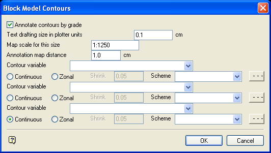
Block Model Contours panel
Annotate contours by grade
Select this check box to annotate the major contours with the grade (minor contours are not annotated).
The following options are available when annotating contours:
Text drafting size in plotter units
Enter the size, in plotter units, of the text. This will be the size of the text on the print out. If the font is a transformable font, i.e. a scaled font, then the size will be in relation to the map scale.
Annotations lie in a straight line, i.e. the text does not curve. The font used for the annotations is specified through the Defaults : 2D Text section of the Tools > Preferences option.
Map scale for this size
Enter the map scale for the text annotations.
Example: If the size is set to 0.30 and the map scale to 1:100, then the text will appear on the screen the same size as an object that is 30 units tall. Changing the scale, in either this option or the File > Plot > Plot All option, to 1:1000 results in the text appearing as 300 units. Changing the scale to 10 000 results in a text size of 3000 units and so forth.
Annotation map distance
Enter the separation distance (in plotter units) between annotations on the same contour line. Remember though, only the major contours are annotated. The distance must be at least 10 times the character height.
Contour variable
Enter, or select from the drop-down list, the name of the variable (data field) to be contoured. Up to three variables can be specified.
Either continuous contours or zonal contours can be calculated. Zonal contours groups areas of the same code, for example geological zones/weathering etc.
Shrink factor
Only applicable to zonal contours
Enter the shrink factor. Specifying a shrink factor allows you to shrink the block markers to ensure that the edges do not overlap. The factor (or gap) is entered in plotter units. Valid values for the shrink factor are between 0 and 1.
Scheme
Select the colour legend to be used for the variable.
Line type
Select the line type to use for the variable.
Natural Ground Contours panel
The Natural Ground Contours panel displays when the Use ground contours outside pit limit check box has been checked.
You can use either the existing triangulation or build a new one. If you select to build a new one, then the Triangulation panel displays upon completion of the current panel.
Refer to the Model > Triangle Surface > Create option for a detailed description of the Triangulation panel.
Ground contour colour
Select the colour for the major contour of the surface triangulation.
Ground contour line type
Select the line type to use for the contour.
Use smooth contouring
Select this check box to control the degree of subcelling. Subcell values are determined from 5th order spline patches. A subcell resolution of 1 gives 4 subcells, a resolution of 2 gives 16, a resolution of 3 gives 64 etc.
The degrees of subcelling available are:
-
-
Normal smoothing
This option performs contouring with a subcell resolution of 4. -
Extra smooth
This option performs contouring with a subcell resolution of 5. This is the slowest. -
Less smooth
This option performs contouring with a subcell resolution of 3. This is the quickest method.
-
Once a smooth operation has been specified, you can then enter the contour filtering value. This value is used to filter surplus points in the contour strings. The surplus points are produced as a result of smoothing a splined surface and producing subcells.
Annotate ground contours
Select this check box to annotate the ground contours.
The following options are available when annotating ground contours:
Text drafting size in plotter units
Enter the size, in plotter units, of the text. This will be the size of the text on the print out. If the font is a transformable font, i.e. a scaled font, then the size will be in relation to the map scale.
Annotations lie in a straight line, i.e. the text does not curve. The font used for the annotations is specified through the Text Defaults section of the Tools > Preferences option.
Map scale for this size
Enter the map scale for the text annotations. For example, if the size is set to 0.30 and the map scale to 1:100, then the text will appear on the screen the same size as an object that is 30 units tall. Changing the scale, in either this option or the File > Plot > Plot All option, to 1:1000 results in the text appearing as 300 units. Changing the scale to 10 000 results in a text size of 3000 units and so forth.
Annotation map distance
Enter the separation distance (in plotter units) between annotations on the same contour line. Remember though, only the major contours are annotated. The distance must be at least 10 times the character height.
Click OK.
A list of matching triangulations is then displayed. From this list, pick the triangulations that you want to section. Selections can be undone by picking the triangulation again. You will also need to specify a colour and pattern for each triangulation.
Midbench Contours panel
The Midbench Contours panel displays when the Use midbench contours of triangulations check box has been enabled (checked).
Model list
Enter the name of the triangulation whose mid benches are to be used. Mid benches of more than one triangulation can be used. Use * (multiple character wildcard) to obtain a list from which you select the required triangulations. For each selected triangulation you will need to enter a name for the contour, the colour and a pattern. The default name is the file identifier (<tfi>) of the selected triangulation.
Use smooth contouring
Select this check box to control the degree of subcelling. Subcell values are determined from 5th order spline patches. A subcell resolution of 1 gives 4 subcells, a resolution of 2 gives 16, a resolution of 3 gives 64 etc.
The degrees of subcelling available are:
-
-
Normal smoothing
This option performs contouring with a subcell resolution of 4. -
Extra smooth
This option performs contouring with a subcell resolution of 5. This is the slowest method. -
Less smooth
This option performs contouring with a subcell resolution of 3. This is the quickest method.
-
Contour filtering (Applicable only if one of the smoothing options has been selected)
Enter the contour filtering value, which allows you to filter surplus points in the contour strings. The surplus points are produced as a result of smoothing a splined surface and producing subcells.
Annotate contours by triangulations
Select this check box to annotate the contours.
Text drafting size in plotter units (Applicable only if annotating contours)
Enter the size, in plotter units, of the text. This will be the size of the text on the print out. If the font is a transformable font, i.e. a scaled font, then the size will be in relation to the map scale.
Annotations lie in a straight line, i.e. the text does not curve. The font used for the annotations is specified through the Text Defaults section of the Tools > Preferences option.
Map scale for this size
Enter the map scale for the text annotations. For example, if the size is set to 0.30 and the map scale to 1:100, then the text will appear on the screen the same size as an object that is 30 units tall. Changing the scale, in either this option or the File > Plot > Plot All option, to 1:1000 results in the text appearing as 300 units. Changing the scale to 10 000 results in a text size of 3000 units and so forth.
Annotation map distance
Enter the separation distance (in plotter units) between annotations on the same contour line. Remember though, only the major contours are annotated. The distance must be at least 10 times the character height.
Calculate Reserves panel
The Calculate Reserves panel displays when the Calculate mining reserves check box has been checked.
Minimum block area
Mining blocks with an area less than this tolerance will not have their reserves calculated.
Text drafting size in plotter units (Applicable only if annotating contours)
Enter the size, in plotter units, of the text. This will be the size of the text on the print out. If the font is a transformable font, that is a scaled font, then the size will be in relation to the map scale.
Annotations lie in a straight line, i.e. the text does not curve. The font used for the annotations is specified through the Defaults : 2D Text section of the Tools > Preferences option.
Map scale for this size
Enter the map scale for the text annotations. For example, if the size is set to 0.30 and the map scale to 1:100, then the text will appear on the screen the same size as an object that is 30 units tall. Changing the scale, in either this option or the File > Plot > Plot All option), to 1:1000 results in the text appearing as 300 units. Changing the scale to 10 000 results in a text size of 3000 units and so forth.
Click OK.
You will then need to select a category by which to select the lines and polygons that define the mining blocks. The shapes of the mining blocks will be constructed by overlaying the selected objects and building polygons from them. The calculated reserves are shown at the centroid of each mining block.

