Tutorial - Building a New Block Model
In this tutorial, you will construct a block model from beginning to end using the Thor dataset. Familiarity with basic Vulcan techniques regarding the creation of points, lines, polygons, and triangulations are necessary. However, this tutorial assumes no prior knowledge of the modeling concepts or methods described below. There are detailed explanations along with numerous screen shot images provided to help guide the user visually through each process in a step-by-step format. Itdoes notinclude techniques for flagging the ISIS database nor does it explain estimation methods.
The dataset for this tutorial is in the thorData.7z file. (Click the link to download the dataset.)
There are five files associated with a block model:
| .bmf | The block model file itself. |
| .bdf | The block definition file containing all the parameters defining the block model. |
| .bef | The block estimation file that contains the calculation parameters. |
| .ber | The estimation run file. |
| .bcf | The block calculation file that contains customized scripts. |
Note: Not all block models require block calculation files.
By the time a block model is complete all of these files will be used, with the exception of block calculation files.
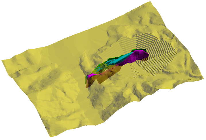
To begin, load the triangulations ore_tq1.00t, ore_tq1a.00t, ore_tq2.00t and topo_with_pit.00t. You should see something like this when looking in plan view.
Next, navigate to Block > Construction > New Definition... This will open up the Block Construction panel.
Continue to Section One - Orientation/Schemes.
Section One - Orientation/Schemes
Section One - Orientation/Schemes
In the first window of the Block Construction panel you will need to set parameters for the block model's origin, rotation and block size scheme.
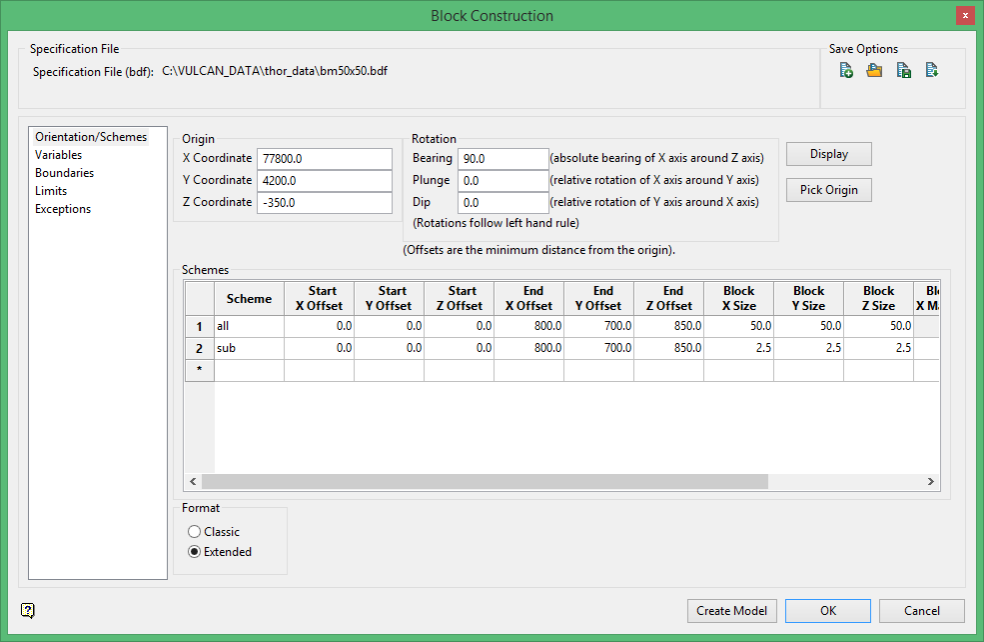
Origin
The first step is to pick the origin. The origin is an arbitrary point used to define the start of the offsets in the scheme and the pivot for the rotations. The origin point, offsets and rotations are used in conjunction with the Parent scheme to define the position in space of the block model. It may be useful to think of the origin point as the minimum coordinate of the X, Y and Z axis, that is, origin = (minX, minY, minZ).
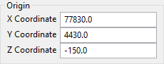
Click  , and then click somewhere near the example below.
The X, Y and Z Coordinate fields will automatically populate. Round the numbers to the nearest tens unit to simplify things and adjust the Z coordinate from 0 to -150.0. Now the origin should look similar to the following:
Rotation
The bearing refers to the rotation of the X axis around the Z axis. It is an absolute bearing which means that a rotation of 0odegrees will result in the X axis oriented due north. A bearing rotation of 90owill result in the X axis oriented due east.
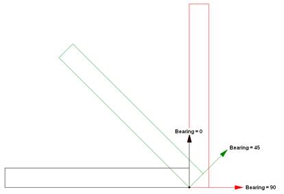
The diagram above displays three separate block models and is shown in plan view. The arrows are on the X axes that are associated with the bearing rotation and are color-coded to match the individual block models. The Y axis is the long axis. Note that the axis of rotation (the black dot) is the origin point. The block model outline with a bearing of 0odegrees shows the X axis pointing due north (toward the top of the page) from the origin; the block model outline with a bearing of 45odegrees shows the X axis rotated 45odegrees clockwise and pointing northeast; and the block model outline with a bearing of 90odegrees is rotated 90odegrees clockwise and is pointing due east.
The plunge refers to the relative rotation of the X axis around the Y axis. When entering the plunge keep in mind that a positive number will rotate counter clockwise and a negative number will rotate clockwise. In the diagram below, the view is taken from the side of the models looking due North.
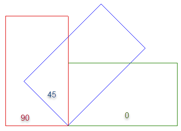
The dip refers to the relative rotation of the Y axis around the X axis. Like the rotation of the plunge directions, a positive number will rotate in a counter clockwise direction while a negative number will rotate in a clockwise rotation.
For this block model the rotations will not be adjusted. Leave the default settings as they are.
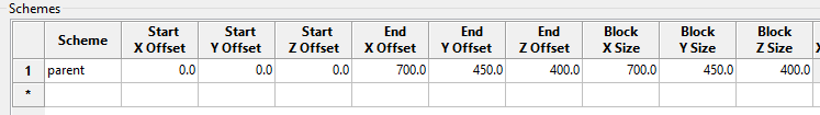
Schemes
The schemes refer to block sizes and offsets. Offset refers to the distance from the origin. The Start Offsets will be 0 since you will be starting at the point of origin. To determine the amount of End Offsets needed for your model, measure from the origin to a point just passed the ore shapes in the X, Y and Z directions using the ![]() icon. The idea is to measure the overall length needed to contain the area of interest in the X direction (East - West), the Y direction (North - South), and in the Z direction (elevation). For measuring the distance in the Z direction you will need to reorient the view so you are looking at the deposit from the side.
icon. The idea is to measure the overall length needed to contain the area of interest in the X direction (East - West), the Y direction (North - South), and in the Z direction (elevation). For measuring the distance in the Z direction you will need to reorient the view so you are looking at the deposit from the side.
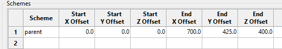
These measurements will be your End Offsets. Enter your results into the schemes table as shown below.
Note: It is always a good idea to test your origin and offset measurements before going any further by building a simplified block model. It can take even a fast computer several hours or longer to build a large block model. Therefore, it is a good idea to make sure that your model covers your area of interest.
Building a simplified block model
The simplest block model is a model that consists of only one block and one variable. To build a block model with only one block you only need to define the block size as being the same size as the model extents, as shown below.
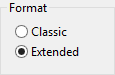
Format
By default, 'Extended' format is selected automatically. Classic format refers to a regularized model, or one that uses blocks that are all the same size. A regular model is needed when blocks need to be deleted. An extended format allows blocks of different sizes to be used in the model. You will not be deleting blocks or creating a regular model in this tutorial. The block model you will be crating will have different sized blocks. Therefore, leave this setting as it is.
Variable setting
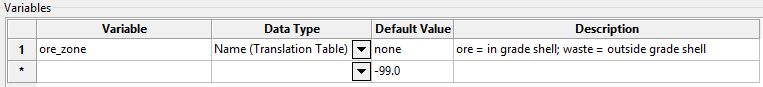
Vulcan requires at least one variable to be declared before it will construct a model. Therefore, you will assign a single variable. You will learn more about variables in the next section of this tutorial, but for now simple fill in the table as shown below.
Building a test model to verify block extents
When you have finished entering the variable information, return to the Orientation/Schemes panel.
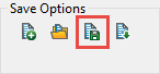
Click the save icon under Save Options.
Click the  button to create the block model. A confirmation dialog window will open showing the Block model name and Definition file name.
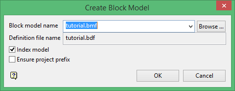
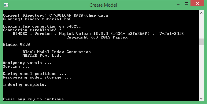
Index model
This check box will be checked by default. Leave it checked. Indexing can be thought of as a way of mapping the location of blocks in a model. In older 'Classic' models if a model was 4Mb in size, then it would take a minimum of 4Mb free disk space to perform the index procedure. However, current 'Extended' models do not require extra disk space when indexing a block model. Furthermore, indexing is an essential component in many advanced functions such as block model addition, regularising and tri-blocking.
Ensure project prefix
Select this check box to use the project code as a prefix when naming the resulting block model. If this check box is checked, then the full name of the resulting block model will be <proj><name>.bmf.
Results
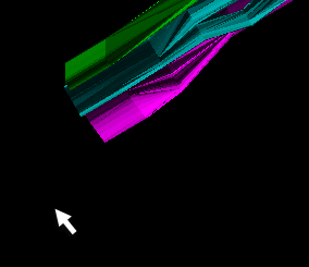
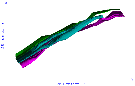
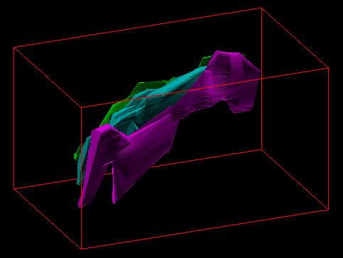
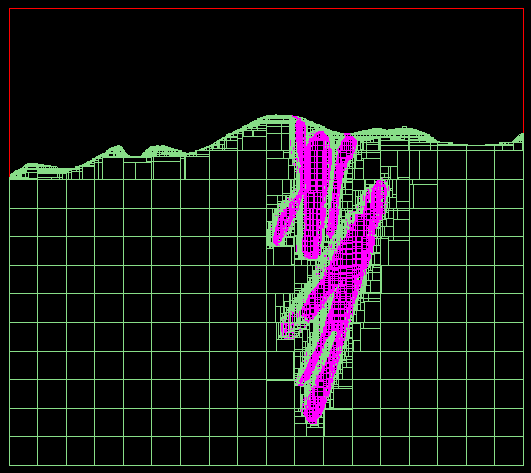
When the model has finished building, rotate it to verify that all areas of interest are contained within the model extents. It should look similar to the image below. If you find part of the triangulations outside of the modelled area then go back and adjust the End Offsets and corresponding Block Sizes, then rebuild the model.
When you are satisfied with the results, you can go back and modify the blocking scheme.
The blocking scheme is one of the most important aspects of the block model and you should take careful consideration before making a decision regarding block sizes. Things to consider are a mine's SMU, the amount of detail in a triangulation, how narrow or how broad a triangulation grows, the amount of memory that is available to your computer system and how fast your CPU is to render your models, etc. Also, remember that you may not be the only person using the models that you build. Often for a mine site, a resource geologist or geostatistician will build the block models, while mine engineers and production geologists will use them on a daily basis to base reserves and plan drill programs.
Parent and sub-block schemes
- The parent block must be a multiple of the sub-blocks.
- The maximum sub-block size must be a multiple of the sub-block minimum size, as well as able to divide evenly into the parent block size. The software will check and adjust sub-block dimensions if they are not multiples.
- The sub-block should always be smaller than the parent block.
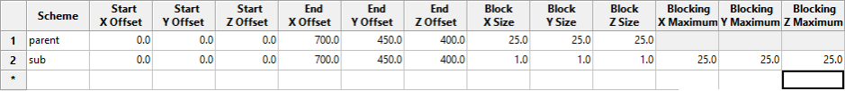
The next step will be to modify the parent scheme to a realistic size instead of using the 'one block test scheme' you used to test the model extents.
For this tutorial, you will use 25m as the parent block size.
Next, enter the sub-block origin, start offset and end offset information exactly like the parent block information.
Enter 1.0 for Block Size. This will be the smallest the sub-blocks will be allowed to get.
Enter 25.0 for Blocking Maximum. This will be the largest the sub-blocks will be allowed to get.
Proceed to Section Two - Variables.
Section Two - Variables
Section Two - Variables
In this section you will define the variables in the block model. These variables may be data fields represented by triangulations, assay values, or any other category contained in the model.
General guidelines:
- T he maximum number of variables per block model is 300.
- The name of a variable can have a maximum of 30 alphanumeric characters.
- A variable name must start with a letter and can only contain alphanumeric characters and/or underscores, for example, '
variable_1. - A variable name can only be entered using lowercase characters.
- Variables to be used as the estimated grade in grade estimation must be of a float or double data type.
Variable naming conventions vary from company to company. Some companies use variable names that are quite descriptive while others are not so clear. That is why the Description column is so important.
There are six data types to choose from:
- Name (Translation Table)
- Byte (Integer*1)
- Short (Integer*2)
- Integer (Integer*4)
- Float (Real*4)
- Double (Real*4)
The Default Value is the value given to a variable that has not been assigned any value yet. It is highly recommended that the default value assigned to a variable not be true values that could actually be found or calculated in a real scenario. For alpha data types a default of 'none' works well, and for numeric data types (-99.0) works well.
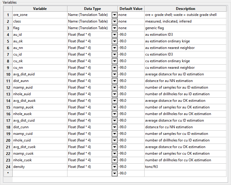
Below is a typical example of a list of variables that might be found in a block model created for a copper and gold deposit. It is not a complete list since it does not take into account waste rock characterization or classification schemes. Nonetheless, it will give you an idea of the type of variables found in a block model. The only variable needed for this tutorial is the one you have already entered in called ore_zone.
Proceed to Section Three - Boundaries.
Section Three - Boundaries
Section Three - Boundaries
This section defines how triangulations are handled by the block model. Here you will link the three triangulations you loaded in the beginning to the block model and assign values to the blocks that will be created inside of the shapes and values to the blocks that will be created outside of the shapes.
Begin by clicking ![]() icon in the Triangulation column and select the ore_tq1.00t triangulation from the list.
icon in the Triangulation column and select the ore_tq1.00t triangulation from the list.
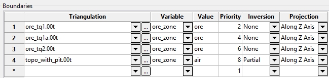
Next, in the Variable column click the ![]() icon and select ore_zone from the list of variables.
icon and select ore_zone from the list of variables.
In the Value column, enter the word ore.
The Priority column is used to determine precedence if two or more triangulations set a value in the same variable in a block model. For example, some solids will represent high grade zones and some will represent low grade zones. The high grade zone may take precedence over the low grade zone. Wherever there is a spatial conflict between the two triangulations, the one with the highest priority takes precedence. When you click in the cell to assign the priority number, an up arrow and a down arrow are displayed. Use these two arrows to increase or decrease the priority level. You can also enter the priority manually.
It is a good idea to assign priority numbers spaced far enough apart that additional triangulations can be added to the list in the middle without having to renumber the entire list. Numbering schemes such as 2,4,6,8..., or 10, 20, 30, 40... are common.
Next, in the Inversion column, select None. This means that for the blocks formed inside the triangulation named ore_tq1.00t, the variable ore_zone will be given a value of ore. If we select an inversion of Complete, then just the opposite will happen and the variable ore_zone will be given a value of ore for all block outside of the triangulation ore_tq1.00t.
A select of Partial deals with 2D surfaces rather than 3D solids. For triangulation that are near to horizontal, you would project along Z axis. The area of interest is then below the triangulation (if None (no inversion) is selected) or above (if Partial or Complete is selected). Since the topo_with_pit.00t is fairly flat you will be dealing with the Partial inversion.
Finally, in the Projection column, select Along Z Axis. The projection does not have any effect when working with solids but it is a good idea to be consistent with your inputs.
Look at the table above and fill out your table as shown.
Proceed to Section Four - Limits.
Section Four - Limits
Section Four - Limits
In this section you will learn how to define limits to the block sizes based on variable values.
In Section One - Orientation/Schemes, you defined the largest block size to be 25m and the smallest block size to be 1m. That means wherever it will fit, a block will remain 25m x 25m x 25m. Near the boundaries of the shapes, or where the shapes become too narrow to contain a block size of 25m x 25m x 25m, the block will be divided up into smaller and smaller increments until it is 1m x 1m x 1m.
The 25m blocks are fine for this particular model because we a not concerned with the area outside of the ore shapes.. The small, 1m blocks, are fine because they allow the shapes to be defined in good detail. However, you need a method of assuring that sufficient detail is obtained inside the ore shapes that allow good grade control, and for that 25m is too large. That is where assigning limits comes in. You will now assign a condition to the blocks that limits the block size to 5m x 5m x 5m if the variable ore_zone has the value of ore assigned to it.
Click the ![]() icon in the Variable column and select ore_zone from the list of variables.
icon in the Variable column and select ore_zone from the list of variables.
Next, enter ore into the Value column.
Finally, enter 5.0 into the Max X Block, Max Y Block and Max Z Block as shown below.
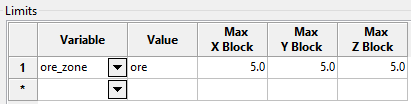
As the model is being built, all blocks inside the three triangulations will be flagged and the variable ore_zone will be given the value ore. Then, when the model resizes the blocks to cut them against the triangulations it will look to see if the variable ore_zone has the value of ore assign to it. If it does, then it will limit the size of the block to 5m x 5m x 5m.
Section Five - Exceptions
Section Five - Exceptions
This section allows you to assign conditions to cells that you don't want stored, that is, any cell criteria that matches an exception will not be stored in the block model. Another way to think of Exceptions is to think of them this way: "Make all blocks except these..."
Not all models use exceptions. In fact, many models you build will not use them. However, in this model you will define an exception that deletes all blocks above the surface of your topographic layer.
In Section Three - Boundaries, you assigned the value of 'air' for the variable ore_zone for all blocks above the topo_with_pit.00t triangulation. Since you will not need the blocks representing air, you can delete them from the model. Therefore, you can write a condition that states when ore_zone equals the value 'air' delete the block. This is how you do it.
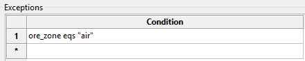
The condition has the syntax of <variable><operator><value>. The operator eqs means 'string equal to'. It is used whenever the value consists of characters instead of numbers.
Now you have completed your block definition file and are ready to save and build your block model.
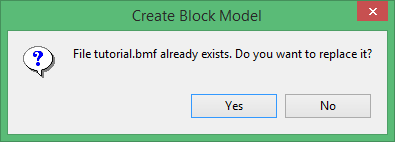
Click save.
Click the button.
A warning will let you know that a model already exists with the same name. That is your test model. Click yes to continue.
A dialog screen will appear showing the progress of the build. Click any key when prompted.
You can view the finished block model by loading it as a dynamic model (see Related Topics below).
Related topics

