Set Up
Use Set Up to set the defaults for the options used through the Development submenu. Once this option has been completed, the specified settings are saved to the Underground Development preferences file (UGDEV.prefs ). This file will be stored in your user profiles area, for example 'C:\Documents and Settings\<user name>'. If the preferences file does not exist, then the Set Up option can be used to create one.
Instructions
On the Underground menu, point to Development, and then click Set Up to display the Underground Development Setup panel.
The Underground Development Setup interface uses the following tabs:
-
Drive Setup
-
Point Annotations
-
Line Annotations
-
Font Settings
-
Arrow Settings
-
Cost Benefit Analysis
Drive Setup
Drive Defaults
Enter the drive width, height to back, depth to floors, curvature radius and gradient values. These are the default measurements that appear in later Development panels. The unit of measurement for the drive width, height and curvature radius is set in the .dg1 file.
The gradient can be entered as a percentage, a ratio, in decimal degrees or in gradian units. To do so, select the appropriate angle format button and enter the value. The format of <negative value>:<value> must be used when entering negative ratios, for example '-1:7'.
Example: Enter a gradient value of 50%, select the % button and enter '50'. Select a different angle format button to convert a value.
Point Annotations
Use the Point Annotations tab to specify the annotation method for points, as well as the layer in which to store the annotations. Points can be annotated with their X/Y/Z coordinate, object name and description, W tag, point name, point number, and a comment. These specifications will be used by the Point(s) Annotation option.
Labelling
Single point label : Select this option if you only want to annotate a single point in a chosen object. You will be required to indicate the point to annotate when annotating points through the Point(s) Annotation option.
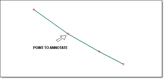
Figure 1 : The Original Object
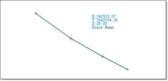
Figure 2 : The Resulting Annotation
Multiple point label : Select this option if you want to annotate a number of points in a chosen object. You will be required to indicate the annotation range when annotating points through the Point(s) Annotation option. Any points that fall in this range will be annotated.
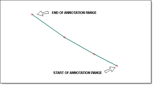
Figure 3 : The Original Annotation
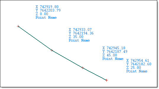
Figure 4 : The Resulting Annotations
Annotation to Include
This section is used to define the attributes in the resulting point annotation block.
|
Data |
Defines what point attributes are to be included in the annotation block.
|
||||||||||||||
|
Order |
Defines what position the point attribute is to have in the annotation block. If an order value is not specified, that is, a field is left blank, then the corresponding attribute will be excluded from the annotation block. |
||||||||||||||
|
NDP |
Defines the number of decimal places to use. This field is not applicable to the Point Name, Point Number, Object Name, Object Name and Comment data attributes. |
||||||||||||||
|
Prefix |
Allows you to assign a prefix to the point attribute. The prefix can be up to 3 alphanumeric characters in length. |
||||||||||||||
|
Space |
Allows you to insert a space after the prefix. |
||||||||||||||
|
Suffix |
Allows you to assign a suffix to the point attribute. The suffix can be up to 3 alphanumeric characters in length. |
||||||||||||||
|
Space |
Allows you to insert a space after the prefix. |
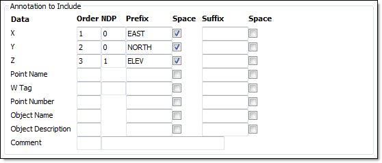
Figure 5 : Annotations to Include
Figure 6 : The Resulting Annotations
Placement
Interactive placement : Select this option to indicate the position at which to place the point annotation. You will be required to indicate the annotation position when annotating points through the Point(s) Annotation option.
Predetermined offset : Select this option to offset the annotation block by a specific distance. You will need to specify the offset distance in the X and Y direction. A 5 metre offset (in the X and Y direction) has been applied to the point annotations in the following diagram.
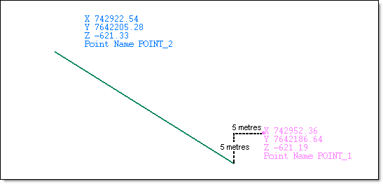
Figure 7 : Offsetting Point Annotations
Options
Framed : Select this check box i f you want to frame the annotation block. The frame will be assigned a group code of "FRAME' and an object name of 'UG_BOX'.
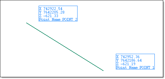
Figure 8 : Framing the Annotations
Rubber band to data point : C heck this box to draw a line between the data point and the annotation block. The line used to connect the annotation block to the data point will be assigned a group code of ' RUB_BAND' and an object name of 'UG_LINE'.
T he Rubber band to data point check box can only be checked when using true type fonts.
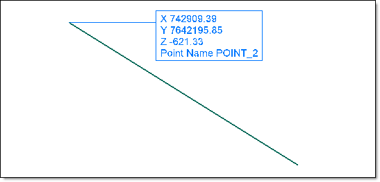
Figure 9 : Connecting the Annotation Block to the Data Point
Save each line of text as a separate object : Select this check box if you want to save each line of text as a separate object. If this check box is not enabled, then the annotations will be stored as a single object.
The Save each line of text as a separate object check box can only be selected when using true type fonts.
Layer Naming Options
Select layer from list : Enter, or select from the drop-down list, the name of the layer that will be used to store the annotations. The maximum size of a layer name is 40 alphanumeric characters (spaces are not allowed).
If you select an existing layer that is loaded, then the annotations will be appended to this layer. If you select an existing layer that is not loaded, then you will need to confirm whether you want to load the layer or replace it, that is, overwrite its contents.
Use annotated object's layer : Select this option to save the annotations in the layer that contains the object you have chosen to annotate.
Use current working layer : Select this option to save the annotations in the current working layer.
Line Annotations
 Use the Lines Annotations tab to specify the annotation method for lines, as well as the layer in which to store the annotations. Lines can be annotated with length, bearing, gradient, object name and description, and a comment. These specifications will be used by the Line(s) Annotation option.
Labelling
Label each segment
Select this option to label each segment withing a selected line object.
Label overall change
Select this option to label the overall change in a selected line object. The information displayed in the annotation block can either be reported as a sum of all segments or it can be reported from one point of the selected line object to another.
Length = Directly from start to end
Select this option to report on the length between two nominated points. The average bearing and grade will be included in the resulting annotation block.
Length = Sum of segments
Select this option to report on the total length of the line segments that fall between two nominated points. The average bearing and grade will be included in the resulting annotation block.
Annotation to Include
This section is used to define the attributes in the resulting line annotation block.
| Data |
Defines what line attributes are to be included in the annotation block.
|
||||||||||||
| Order | Defines what position the line attribute is to have in the annotation block. If an order value is not specified, that is, a field is left blank, then the corresponding attribute will be excluded from the annotation block. | ||||||||||||
| NDP | Defines the number of decimal places to use. This field is not applicable to the Object Name, Object Name and Comment data attributes. | ||||||||||||
| Type | Defines the format in which the data item is to be expressed. The drop-down lists contain the following formats:
|
||||||||||||
| Prefix | Allows you to assign a prefix to the line attribute. The prefix can be up to 10 alphanumeric characters in length. | ||||||||||||
| Space | Allows you to insert a space after the prefix. | ||||||||||||
| Suffix | Allows you to assign a suffix to the line attribute. The suffix can be up to 3 alphanumeric characters in length. | ||||||||||||
| Space | Allows you to insert a space after the prefix. |
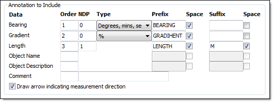
Figure 10 : Annotations to Include
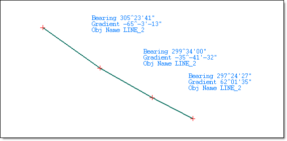
Figure 11 : The Resulting Annotations
Draw arrow indicating measurement direction
Select this check box to display an arrow that indicated the measurement direction. The size of the arrow in the resulting annotation block is defined through the Arrow Settings tab .
The Draw arrow indicating measurement direction check box can only be checked when using the Parallel to line option.
Placement
Interactive placement
Select this option if you want to indicate the position at which to place the point annotation. You will be required to indicate the annotation position when annotating lines through the Line(s) Annotation option.
Predetermined offset
Select this option if you want to offset the annotation block by a specific distance. You will need to specify the offset distance.
Parallel to line
Select this option to place the annotation block parallel to the line segment.
Horizontal
Select this option to place the annotation block horizontal to the line segment.
Options
Framed
Select this check box to frame the annotation block. The frame will be assigned a group code of 'FRAME' and an object name of 'UG_BOX'.
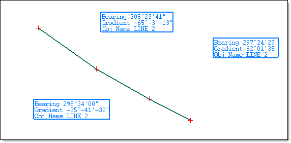
Figure 12 : Framing the Annotations
Rubber band to data point
Check this box to draw a line between the data point and the annotation block. The line used to connect the annotation block to the data point will be assigned a group code of 'RUB_BAND' and an object name of "UG_LINE'.
The Rubber band to data point check box can only be checked when using true type fonts.
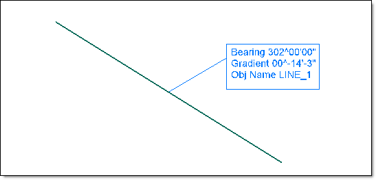
Figure 13 : Connecting the Annotation Block to the Data Point
Save each line of text as a separate object
Select this check box to save each line of text as a separate object. If this check box is not enabled, then the annotations will be stored as a single object.
The Save each line of text as a separate object check box can only be checked when using true type fonts.
Layer Naming Options
Select layer from list
Select the layer that will be used to store the annotations.
The drop-down list contains the names of all layers found in the currently open design database. If you select an existing layer, then the resulting data will be appended to the nominated layer. If you enter the name of an existing layer that is not currently loaded, then you will need to confirm whether you want to load the layer or replace it, that is, overwrite its contents.
To create a new layer, enter the layer name. The layer name:
- may contain up to 40 characters.
- must begin with an alphanumeric character [0-9] or [a-z].
- cannot include spaces.
- can include hyphens [ - ], plus signs [ + ], underscores [ _ ], periods/dots [. ].
- can include the special characters of ÁÂÃÀÇÉÊÍÓÔÕÚÜÑ that are used in the Spanish and Portuguese languages.
Use annotated object's layer
Select this option to save the annotations in the layer that contains the object you have chosen to annotate.
Use current working directory
Select this option to save the annotations in the current working layer.
Font Settings
Label Font
Select the type of font for the annotations, that is, fixed or true type font.
Fixed
Select this option to use a non-transformable font. Once selected, you will be required to pick a font from the drop-down list. You will have the choice of 'Small', 'Normal', 'Medium' and 'Large'.
Fixed fonts remain the same size on the screen regardless of the current zoom and always appear 'face on' (horizontal) regardless of the drafting angle. The drafting angle is only followed when a hard copy plot is produced.
True Type
Select this option to use a true type font. Once selected, you will be required to pick a font from the drop-down list. The drop-down list will display all of the true type fonts loaded onto your computer (it is independent of Vulcan). We recommend that you use a true type font when trying to produce a plot that appears exactly the same as the screen display.
Note: You will need to use true type fonts to use the Rubber band to data point and Save each line of text as a separate object check boxes (under the Point Annotations and Line Annotations tabs).
Size of text on plot
Enter the size, in plotter units, of the text on the plot. The specified value will also be used to define the size of the point markers on the plot.
Drafting scale
Enter the drafting scale as a ratio, which is used in conjunction with the text size entered above.
Example: If the text size is set to '0.10' (10cm), and the drafting scale ton '1:1250', then the text will appear on the screen the same size as an object that is 125 units long. Changing the scale, through either this option or the File > Plot > Plot All option to '1:1000' will result in the text appearing the same size as an object that is 100 units long. Changing the scale to '1"10 000' results in a text size of 1000 and so forth.
Arrow Settings
Arrow settings
Use font size and scale
Select this option if you want the arrow to be proportional to the text displayed in the line annotation block.
Absolute size
Select this option if you want the arrow's head to have a fixed size. Once selected, you will be required to specify the arrow length and arrow width (both in plotter units) as well as the scale (this refer to the scale used when drawing the arrow head on the screen).
Relative size
Select this option if you want the arrow's head to have a size relative to the length of the arrow instead of an absolute size. The longer the arrow, the bigger the arrow's head. The arrow head and width values need to be entered as a percentage of the arrow length.
Cost Benefits Analysis
This panel to configure the variables that are to be used when using the Cost Benefits Analysis option (under the Underground > Analyse submenu).
Currency Parameters
Currency Units
Specify the currency unit that will be used in the reports. The currency symbol can be selected from the available drop-down list or manually entered. Custom symbols (a maximum of 3 characters) can also be entered.
Development Parameters
Development Costs
Enter the cost per linear unit to mine, for example $3000 per metre of advance. The unit of measure used is controlled through your project specification file (.dg1).
Development Efficiency
Enter the development efficiency rating.
Maximum Efficiency
Enter the maximum decline allowed over long distances in the operation. The gradient value can be entered as a percentage, a ratio, in decimal degrees or in gradian u nits. To do so, select the appropriate angle format button and enter the value. The format of <negative value>:<value> must be used when entering negative ratios, for example '-1.7'.
Example: To enter a gradient value of 15%, select the % button and enter '15' '. Se lect a different angle format button to convert a value.
Production Parameters
Production Price
Enter the revenue per unit of product. The volume units that will be used is controlled through the drop-down list.
Production Cost
Enter the cost to mine a unit of material. You will also need to select the desired unit (for example per metric tonne, per kilogram, per ounce, etc.) from the drop-down box.
Recovery
Enter the percentage of product that is recoverable.
Dilution
Enter the percentage of material that will dilute the mining.
Production Efficiency
Enter the production efficiency rating.
Reporting
Create Microsoft Excel Report
Check this box to output the information to an Excel spreadsheet (.xls).
Create ASCII Report
Select this check box to output the information to an ASCII text file (.txt). The name and storage location for the resulting files is specified through the Cost Benefits Analysis option.
Click OK.
The settings are then saved to your UGDEV.prefs file.

