Level Layout
Use this option to quickly lay out underground development connecting optional level access points and a group of stope triangulations. Level Layout generates near-optimal designs that seek to minimize the total cost of constructing the level access network and hauling ore from stopes. The option allows interactive manipulation of the initial output designs at each level to work around unique design requirements.
Note: This option replaces the Level Designer and Decline Optimiser options that were available in Vulcan prior to version 2023.4.
Instructions
On the Underground menu, point to Development, then click Level Layout.
Parameters
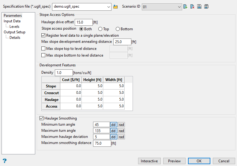
Use this pane to set preferred stope access, development, and haulage options.
To quickly see a preview of the initial underground development generated with this option, you need only to populate the Specification file (*.ugll_spec) and Scenario ID fields, in addition to selecting stope triangulations of interest in the Input Data pane before clicking Preview at the bottom of the interface. All other panel options can be left as defaults for the preview and refined as needed.
You can click Interactive as well to manipulate the initial development instead of only previewing. See more information in the Interactive Editing Dialog (Optional) section.
Follow these steps:
-
Select a Specification file (*.ugll_spec) from the drop-down list, or enter a file name to create a new one. To select or create a specification file outside of the current working directory, click
 to navigate to another location.
 -
Select a Scenario ID from the drop-down list, or click
 New to enter a new ID.
You can make changes to an existing scenario, then click
 Save As to save the edited version under a new name. This allows you to transfer all the parameter settings from the current panel settings to the new scenario without needing to make selections again.
Click
 Save to save any changes to the scenario after updating parameter settings in the panel before closing out of the panel. You can also select
  Delete to remove a nominated scenario.
 -
In the Stope Access Options section, enter the initial offset from the edge of a stope shape to the haulage drift connection in the Haulage drive offset field. This is the minimum length for the crosscut into the stope.
-
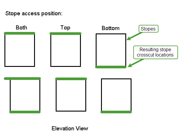
Specify which side of stope shapes will be used to create levels (in automatic mode) by selecting Both, Top, or Bottom for the Stope access position. This option also determines where crosscuts will be generated.
-
Both will combine the extents of the bottom of a stope above and the top of a stope below to create a single crosscut. The resulting crosscut will be placed along the top stope surface for levels where there are stopes present above and below, and along the bottom surface if there is no stope below the level.
-
Top will use the extents of the top surface of a stope only to create a crosscut (ignoring the bottom) and the crosscut will be located along the top stope surface.
-
Bottom will use the extents of the bottom surface of a stope only to create a crosscut (ignoring the top) and the crosscut will be located along the bottom stope surface.
-
-
Select the Register level data to a single plane/elevation checkbox if you want to register all stope crosscuts and output data for each level to a single plane/elevation.
-
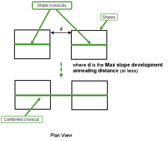
Enter the maximum separation distance used to combine collinear stope crosscuts into a single crosscut in the Max stope development annealing distance field.
-
Select the Max stope top to level distance checkbox if you want to specify the maximum distance between the top surface of a stope and a level that it can be assigned to. This option is only available if you have selected the Both or Top option for Stope access position.
-
Select the Max stope bottom to level distance checkbox if you want to specify the maximum distance between the bottom surface of a stope and a level that it can be assigned to. This option is only available if you have selected the Both or Bottom option for Stope access position.
-
In the Development Features section, enter the Density that will be used for calculating tonnages of generated development.
-
Use the grid to define the Cost, Height, and Width of each development type (i.e. Stope, Crosscut, Haulage, and Access). These values are used for creating wall outlines, primitives, volume, tonnages, and development cost reports (see more information in the Details section of the panel).
Note: There is a limit of 1,000,000 for all fields in this grid.
-
Select the Haulage Smoothing checkbox if you want to apply the following parameters to smooth the haulage configuration:
-
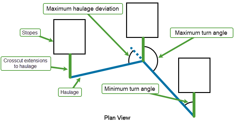
Enter the minimum angle for turning in from haulage to a crosscut in the Minimum turn angle field in either decimal degrees (dd) or radians (rad).
-
Enter the maximum angle for turning in from a haulage to a crosscut in the Maximum turn angle field in either decimal degrees (dd) or radians (rad).
-
Enter the maximum angle from one haulage segment to another in the Maximum haulage deviation field in either decimal degrees (dd) or radians (rad).
-
Enter the maximum distance between two haulage nodes to treat them as a single entity for smoothing in the Maximum smoothing distance field. Smaller values will smooth data in more discrete sections where larger values will treat more of a level as a single entity.
-
Input Data
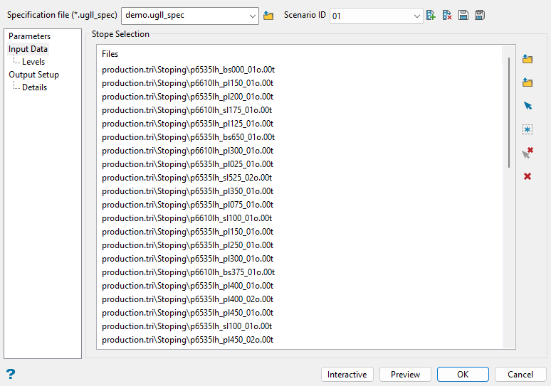
Use this panel to select your stope shape files. The option support selecting triangulations or selection files, or using interactive picking from the screen.
Follow these steps:
-
Use the icons in this pane to select the desired stope shape files.
Click
 Browse for Triangulations to choose the desired triangulation/selection file(s) from the Open panel. If you choose selection files with this option, they will be parsed and listed out as individual triangulation files. Therefore, even if the contents of the selection file changes in the future, the Level Layout specification file (
.ugll_spec) will retain the same list of triangulations generated at the time of saving. Browse button (Open panel)
In the Open panel, click on the name of the file(s) you want to select from the current working directory list. Use the
 icons to go to the last folder visited, go up one level, or change the way details are viewed in the window, respectively.
When using wildcard characters, type
*> for multi-character and?> for single character. To highlight multiple list items at once, use the left mouse option in combination with theShiftkey (this is for items that are adjacent in the list; for non-adjacent items, use theCtrlkey and the left mouse option).Move the items to the selection list on the right side of the panel.
- Click the
 button to move the highlighted items to the selection list on the right.
 - Click the
 button to remove the highlighted items from the selection list on the right.
 - Click the
 button to move all items to the selection list on the right.
 - Click the
 button to remove all items from the selection list on the right.
Select the Save Selection checkbox to save the selection list (the right-hand side of the Open panel), in a nominated selection file (
.sel).Click OK in the Open panel to complete file selection.
To choose selection files (
.sel) without listing out the associated triangulation files, thus respecting changing content of selection files in the future, click Browse for Triangulation Selection Files, which allows the same panel controls as the previous option. Alternatively, use
 Screen Pick or
  Select All Loaded Triangulations icons to select from triangulations loaded on screen.
 To remove an item from the list, select the file and click
 Remove Selected Files. To remove all files from the list, click
  Clear All Files.
 - Click the
-
Advance to the next pane of the Level Layout interface once you have selected the desired stope shape files.
Levels
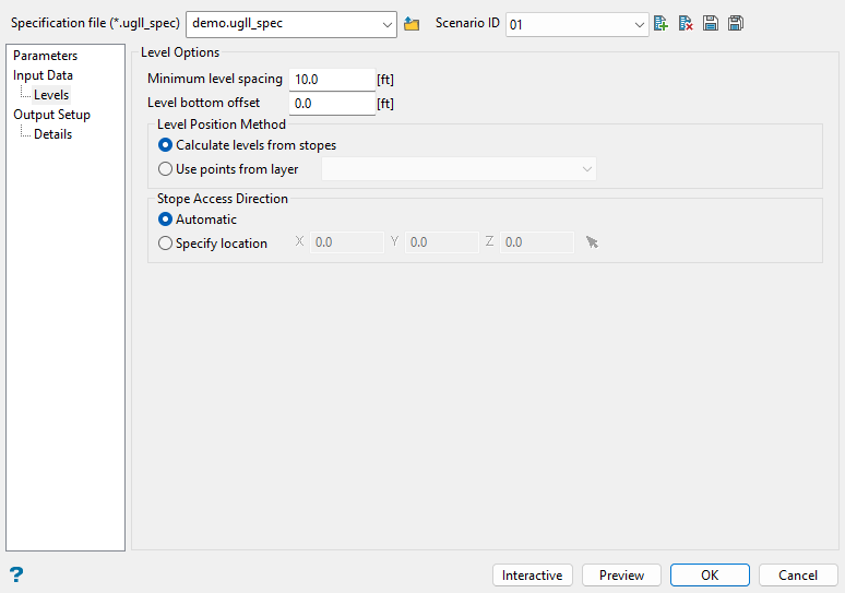
Use this pane to set preferred level parameters, including spacing, offset, position, and access direction.
Follow these steps:
-
Enter the minimum spacing between two levels in the Minimum level spacing field. Levels that are detected to be closer together than this spacing will be removed. Filtering is performed from the bottom elevation working up, measuring to the next level. If the spacing is too small, that level is skipped and the next level will be used.
-
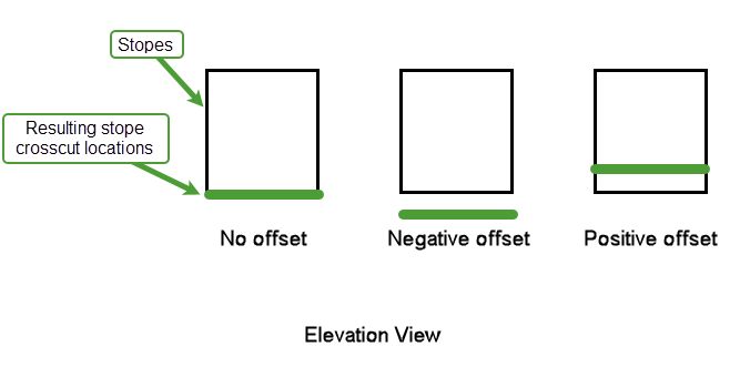
Enter the desired offset for levels aligned to a stope bottom surface in the Level bottom offset field, which will only be considered when the Stope access position in the Parameters pane is set to either Both or Bottom. This offset will be applied to all levels in Bottom mode and only to levels where no associated stope top is found when using Both. Enter negative values to move the level down and positive values to move the level up.
-
Select either Calculate levels from stopes or Use points from layer for the Level Position Method.
-
Calculate levels from stopes: This option calculates the levels using the stope top or bottom surfaces, based on the Stope access position set in the Parameters pane.
The levels are determined via clustering data and assigning levels to groups of stope shapes, which are then filtered using the Minimum level spacing to ensure the levels are not too tightly clustered.
-
Use points from layer: This option uses a series of single point objects in a nominated layer from the drop-down list to determine where levels will be located. The elevation of the access points determines where the levels will be placed. If levels are too tightly spaced, they will be filtered out by the Minimum level spacing.
Tip: You can build ramps and declines with Underground > Development > Automatic Ramps to create level access points from and save them to a nominated layer for use with this option.
-
-
Select either Automatic or Specify location for the Stope Access Direction.
-
Automatic: When using Calculate levels from stopes, this option will try to estimate which direction stope crosscuts should move toward based on the volume averages.
When using Use points from layer, the access points in the nominated layer are used to determine direction. The stope crosscuts will face towards the access points.
-
Specify location: This option overrides the other direction calculations and designates a point to determine which side of the stopes that stope crosscuts will face towards. You will need to specify the X, Y, and Z location, or select
 to digitise the location on the screen.
-
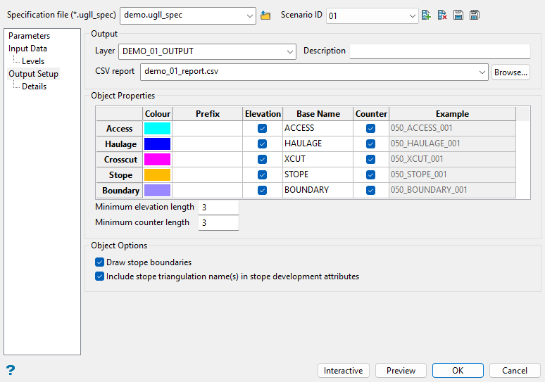
Output Setup
Follow these steps:
-
Specify the Layer for the output objects generated by Level Layout. Select an existing layer from the drop-down list or enter a new layer name.
-
(Optional) Enter a Description for the nominated output layer. The description can contain up to 80 alphanumeric characters and can include spaces. If a description is not entered, a default description will be used instead.
-
Specify a CSV report to save the details of the created development to. Choose from an existing file in the drop-down list, which includes all CSV files in the current working directory, or click Browse... to select a file from another location. To create a new file, enter a new CSV report name.
-
Use the grid to set the output Object Properties including naming and colour controls for each development type, as well as the optional Boundary objects for the stopes.
-
Colour: Double-click on the colours in this column of the grid to select a different option from the current colour table to assign to the respective objects.
-
Prefix: Enter an optional prefix to include in the object name.
-
Elevation: Select this checkbox to include the respective level elevation in the object name.
-
Base Name: Enter the base name of the objects for each development type.
-
Counter: Select this checkbox to include a numbered suffix in the object name to differentiate objects of the same development type and level.
Use the Example column to preview the full object names, which is updated any time a field in the Object Properties section is changed. The Example column also reflects the Minimum elevation length and Minimum counter length field entries, as shown by the number of leading zeros for the elevation and count in the output object names.
-
-
Select the Draw stope boundaries checkbox in the Object Options section if you want the stope boundaries to be drawn with the generated centrelines. The colour and name of boundaries can be adjusted in the Boundary row of the Object Properties grid.
-
Select the Include stope triangulation name(s) in stope development attributes checkbox if you want to include the original stope triangulation names(s) in the stope development object attributes. Multiple triangulation names will be assigned where stope crosscuts are combined via the Max stope development annealing distance option, or where there is overlap.
Details
Follow these steps:
-
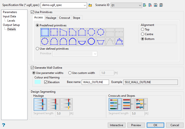
Select the Use Primitives checkbox to select primitives in each development type tab. You will need to choose between using Predefined primitives or User defined primitives.
Note: Sizes defined in the Development Features grid in the Parameters pane for each development type are used for the primitive shapes.
-
Predefined primitives: Select this option to choose a primitive from the displayed collection of predefined geometric shapes.
-
User defined primitives: Select a previously saved primitive specification file (
.pgd) from the drop-down list.See Model > Primitives > Create/Edit Primitives for more information on creating primitives.
You will also need to choose the Alignment for the selected primitives, selecting from Top, Centre, or Bottom with respect to the development object centrelines.
-
-
Select the Generate Wall Outline checkbox to create a wall outline around the centrelines. This will generate a single wall outline object per level. You will need to select either Use parameter widths or Use custom widths with this option:
-
Use parameter widths: Wall outlines will use the Width from the Development Features grid in the Parameters pane for each development type, which is the same width used for primitives.
-
Use custom width: Overrides all wall outlines with a single specified width value.
In the Colour and Naming section, specify the colour for the wall outline and select the Elevation checkbox to include the level elevation as a prefix to the text entered for Name field of the wall outline objects, as shown in the Example field.
-
-
In the Design Segmenting section, select from the Haulage options below:
-
Break between crosscuts: Haulage is split up as one object per connection.
-
Left and right sides: Haulage is a single object for each side of the access intersection. Every haulage fork will start new haulage objects depending on the number of fork branches. For example, if there is a fork that has three branches, then three new haulage objects will be created.
-
Break by length: Haulage segments are discretised/split into a specified Segment length.
-
-
Select from the following options for Design Segmentation of Crosscuts and Stopes:
-
Break at stope boundary: Crosscuts are split at the stope and crosscut boundaries (split at ore/waste contact).
-
Single object: Crosscut is a single object from haulage to the end of the stope.
-
Break by length: Crosscuts are discretised/split into a specified Segment length.
-
Interactive Editing Dialog (Optional)
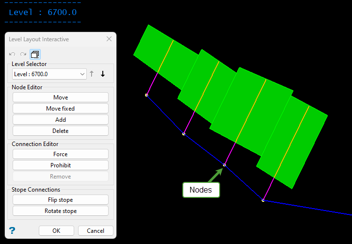
The interactive editor allows manipulation of the initial design generated by Level Layout for each level, as desired. Connections can be forced or blocked while nodes can be added or removed to work around design requirements.
Any interactive edits will re-solve the level where the edit was made while taking into account user parameters. Some of the more complex solving methods are not applied in interactive mode. For example, Vulcan does not reapply haulage smoothing after interactive changes. Additionally, it will not attempt to pathfind around stopes (as done when initially solving all levels).
Also note that objects shown in interactive mode are simplified somewhat for speed/performance and clarity purposes. These simplifications include basic segmentation (i.e. default segmenting for haulage and crosscuts and stopes) and omitting primitives and wall outlines. Once satisfied with your changes in interactive mode, click OK and these details will be applied to objects. Clicking OK in this dialog also completes the Level Layout session and saves outputs.
Follow these steps:
-
When you are satisfied with the selections made in the main panel, select the Interactive button at the bottom of the Level Layout interface. You will then be prompted to choose the initial level to begin the interactive process.
TipButtons in the top section of the interactive editor allow
 Undo and
  Redo of operations, as well as toggling section view on and off by clicking
  .
. Undo/redo will function across levels, so if an operation is performed on one level and the level is changed, undo will be available to change the previous level. When in section view, the level will automatically adjust if an undo/redo action affects a level that is not in the current focus to improve visibility of the change.
-
If you would like to change which level to work with during the interactive process, choose from the Level Selector drop-down list. You may also use the up and down arrows to navigate through the available levels.
-
Use the following options in the Node Editor section to modify haulage nodes. Right-click to exit selection mode in any of these options to return to the interactive dialog.
-
Move: Allows you to move a haulage node without constraint.
-
Move fixed: Allows you to move a haulage node along the orientation of the stope alignment.
-
Add: Allows you to add a new haulage node.
-
Delete: Allows you to delete a haulage node.
-
-
Use the following options in the Connection Editor section to modify connections between haulage nodes. Right-click to exit selection mode in any of these options to return to the interactive dialog.
-
Force: Allows a connection to be forced in, regardless of validity, to help satisfy operational constraints. A forced connection will display a dashed line over it in green (if using the default Vulcan colour palette).
-
Prohibit: Allows a connection to be blocked, even if it might be the shortest route, in order to achieve better operational connections. A prohibited connection will display a dashed line over it in red (if using the default Vulcan colour palette).
-
Remove: Allows a forced/prohibited connection to be removed. Once you select this option, any forced/prohibited connections will be highlighted to provide visibility as to what can be removed.
-
-
Use the following options in the Stope Connections section to change the direction of the stope connection points. Right-click to exit selection mode in any of these options to return to the interactive dialog.
-
Flip stope: Allows individual stopes to be mined from the opposite direction. These flips will not attempt to pathfind around stopes.
-
Rotate stope: Allows individual stopes to be mined from a rotated direction. Each time that you select a stope with this option, the connection point is rotated 90 degrees clockwise around the stope. These rotations will not attempt to pathfind around stopes.
-
-
Once satisfied with your changes in interactive mode, click OK in this dialog to complete the Level Layout session and save outputs. Alternatively, click Cancel to return to the main Level Layout interface. If you select Cancel in the interactive dialog, changes you made in interactive mode will remain but may be overwritten if parameters in the Level Layout panel are changed.
Running the Level Layout option
The Level Layout interface allows you to make changes and preview them on the fly without having to save the design or exit the panel. Click Preview at the bottom of the panel to view the design on screen based on current panel settings.
Note: It is not necessary to preview the design prior to running the Level Layout process. If you preview the design, neither the design nor the scenario will be saved automatically. If you preview the design and then want to save it, you will need to click ![]() Save.
Save.
Click OK to run Level Layout and save outputs. You can also click Cancel to exit the panel without saving changes.
After running, the output report is shown in the Level Layout Console, which includes a summary of counts, lengths, costs, and tonnage for the development types. A more detailed breakdown of this information for each level is saved to the nominated CSV report.

