Create Rings
The Create Rings process is a preliminary step in the creation of blastholes. The Create Rings option to create a series of labelled rings in a ring layer, with their location based on the specified dip angle, ring burden and extents.
Tip: To ensure meaningful reports when using the Report on Layout option, we recommend that you digitise from top to bottom, as well as from left to right, when designing both the stope reference line and the necessary rings. This will mean that the Left and Right values in the report will fit the convention. For example, if you're looking north in a cross section, then west is to the left and east to the right. If you're looking east in a cross section, then north will be to the left and south to the right.
Note: You must be in Plan view in order to create the rings.
This option can also be accessed by selecting the ![]() Create Sections button from the UG Ring Design toolbar.
Create Sections button from the UG Ring Design toolbar.
Click to view related tutorial.
Instructions
On the Underground menu, point to Ring Design, then click Create Rings to display the Create Rings panel.
Layer
Select the layer that will be used to store the section lines.
Description
Enter a description to further define the contents of this layer. The description can be up to 80 alphanumeric characters and may include spaces. If a description is not entered, then a default description will be used instead. If the chosen layer already has an assigned description, the description displays when the layer is selected. Existing layer descriptions can be overwritten.
Default Ring Burden
The ring burden defines the range of the blast from the toe. This value is used to calculate the distance between each ring. It is measured at design height, in a direction tangential to the ring plane, that is, parallel to the reference line. This reference line can be defined by picking an existing line off the screen or digitising it graphically.
Important: Two ring design methods are available and the panel options will be different based on the selection you choose:
Use the Standard design option to generate rings with the same dump size (that is, dip angle) suitable for placement along the length of a regularly shaped stope. Standard ring design is typically used in the standard production phase of an underground mine.
Use the Stand up design option to design a set of rings of varying dump sizes, more suitable for up hole and slash hole mining. The type of stand up design created depends on mining requirements.
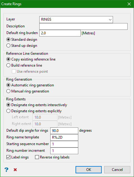
Standard design
Reference Line Generation
Copy existing reference line
Select this option to pick the section reference line from the screen. Check the Create copy of existing reference line check box to copy and use an existing reference line.
Build reference line
Select this option to digitise a reference line. Enable the Use reference point check box to use a reference point.
Ring Generation
Rings can be built, along the complete length of the reference line, automatically or they can be selectively confirmed as the lines are constructed and displayed.
Automatic ring generation
Select this option if you want the rings, along the complete length of the reference line, to be built all at once.
Manual ring generation
Select this option to confirm each ring as it is being generated. You can retain the new ring, ignore it, adjust the step size or stop building rings.
Ring Extents
A ring is defined by left and right distances perpendicular to the reference line. These distances define the extent of the ring and can be specified graphically or by manually entering left and right distances.
Designate ring extents interactively
Select this option to pick two points that define the left and right extents of the sections. Upon completion of this panel, you will be prompted to indicate the extents. Click Cancel when you have finished defining the extents. The Section line extents panel is then displayed.
Designate ring extents explicitly
Select this option to enter the left and right extents for the section lines.
Default dip angle for rings
Enter the default dip for the resulting section lines. The range is -90 to 90.
Ring name template
The section lines will be named sequentially according to the prefix and sequence order. The maximum size of the prefix is 4 alphanumeric characters.
| Block Name | Result |
|---|---|
| R%.D | R1, R2, R3,... |
| R%.3DTK | R001TK, R002TK, R003TK,... |
| %.2D | 01, 02, 03,... |
Starting sequence number
Enter the starting sequence number for naming the section lines.
Example:
Section Name Template: R%.2D
Result:
Strip number increment: 2
Start Strip Number: 10
R10
R12
R14 etc
Ring number increment
This is used in the section name. Each section name will be incremented with the number specified here.
Label rings
Select this check box to display the name of each section line as it is being built.
Reverse ring labels
Select this option to reverse the sequence of the ring labels.
This panel displays the actual distances of the recently defined extents. These values can be modified manually.
Select OK.
Stand up design
Note: Clicking the option for Stand up design will make the panel expand.
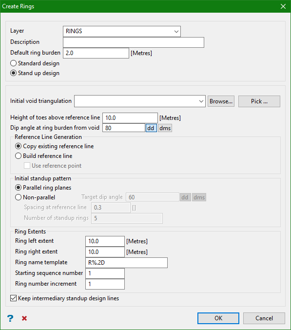
Select Stand up design to create a set of rings of varying dump sizes (that is, dip angles). Stand up rings are typically used in up hole and slash hole mining. The type of stand up design created depends on mining requirements.
Initial void triangulation
Browse for and load the triangulation dataset for the existing void. Alternatively click Pick to pick a triangulation loaded on your screen.
Height of toes above reference
Set the height of the toe from the reference line of the ring.
Dip angle at ring burden from void
Set the angle of the first ring from the reference line in either decimal degree format or in degrees-minutes-seconds, so that the ring is at burden distance from the existing void.
Initial stand up pattern
Select a stand up pattern based on the requirements of your ring design. For more information on stand up patterns, see the diagrams above.
Parallel ring planes
Select this option to create parallel rings with a specified dip angle (dump size) and a distance from each other defined by the toe burden.
As shown in the diagram below, the rings are parallel to each other and set at the same dip angles. The void is represented by the triangulation. The initial ring plane is indicated by the first upward line on the left, which slopes upward based on the dip angle and the burden distance from the void at toe height.
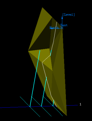
Figure 1 : The rings are parallel to each other and set at the same dip angles.
Non-parallel
Select this option to create rings that are not parallel to each other, and that have increasing or decreasing dip angles (or dump sizes) depending on the function of the rings.
As shown in the diagram below, the non-parallel rings are set at increasing dip angles. The void is represented by the triangulation. The initial ring plane is indicated by the first upward line on the right, which slopes upward based on the dip angle and the burden distance from the void at toe height.
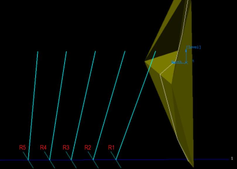
Figure 2 : The non-parallel rings are set at increasing dip angles.
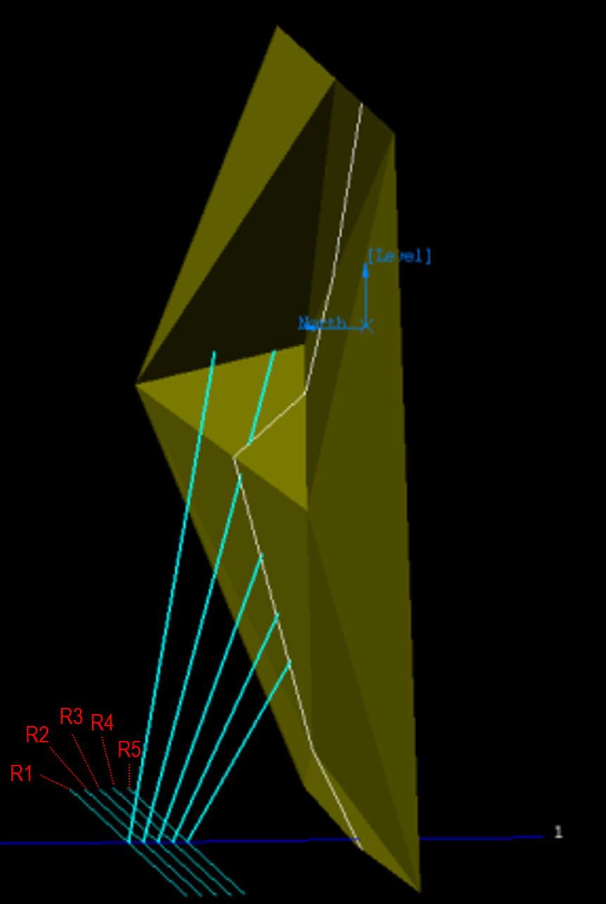
Figure 3 : The non-parallel rings are set at decreasing dip angles.
The following three options are only available when Non-parallel is selected.
Target dip angle
Set the angle of the final ring from the reference line.
Calculate number of rings
Use this to automatically calculate the number of rings that will fit based on the spacing that will fit within the reference line.
Spacing at reference line
Set the spacing of the rings. The option is unavailable if the value for Dip angle at ring burden from void is less than that for the Target dip angle, that is, the dip angle is increasing (or the dump size is decreasing).
Number of standup rings
Set the number of rings in this ring design.
Ring Extents
A ring is defined by left and right distances perpendicular to the reference line. These distances define the extent of the ring and can be specified graphically or by manually entering left and right distances. In most cases, the location of the ring extents is important only in the visual display of a ring.
Ring left extent
Enter the left extent in metres for the section lines.
Ring right extent
Enter the right extent in metres for the section lines.
Ring name template
The section lines will be named sequentially according to the prefix and sequence order. The maximum size of the prefix is four alphanumeric characters.
| Block Name | Result |
|---|---|
| R%.D | R1, R2, R3,... |
| R%.3DTK | R001TK, R002TK, R003TK,... |
| %.2D | 01, 02, 03,... |
Starting sequence number
Enter the starting sequence number for naming the section lines.
Example:
Section Name Template: R%.2D
Result:
Strip number increment: 2
Start Strip Number: 10
R10
R12
R14 etc
Ring number increment
This is used in the ring name. Each ring name will be incremented with the number specified here.
Keep intermediary standup design lines
Select this option to retain intermediary design lines in your ring design model. These lines represent the plane of each ring design.
Click OK.

