Create Stope
Use the Create Stope option to construct a 3D triangulation from strings or polygons that represent stopes.
This option is similar to the Create option (under the Model > Triangle Solid submenu). The main difference is that the Create Stope option allows for the evaluation of reserves while building the triangulation.
Note: A block model must be loaded prior to selecting this option.
Instructions
On the Underground menu, point to Stope Design, and then click Create Stope to display the Create 3D Solid panel.
The 3D triangulations can either be built as a single solid or as separate solids.
Build single solid
Select this option to create a single triangulation. Check the Append resulting triangulation check box to append the new triangulation to a copy of an existing triangulation. The existing triangulation must be loaded onscreen prior to using this option. If a triangulation is not loaded, then a message will be displayed when you try to save the triangulation. Once this message has been accepted, you will be prompted whether or not to save the new triangulation.
Break solid by strings
Select this option to create separate triangulations between each pair of strings or polygons. Once each pair of strings has been selected, you will be prompted for the colour of the triangulation and the shell name.
Check the Construct first end plate and Construct last end plate check boxes to close the beginning and end of the model. Do not check these check boxes if you are joining several triangulations together as you may end up with internal walls that will cause volume problems. The first and last strings must be closed polygons otherwise you may not get the desired results when performing volume and reserve calculations.
Use tie strings
Select this check box to guide the triangulation formation using lines between the polygons.
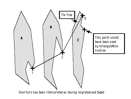
Figure 1 : Forcing the Triangulation with a Tie Line
For complex structures, such as an ore body or stope with folds or overturns, you may need to force the triangulation to follow a path, which is not necessarily the path that Vulcan would choose. This path is defined by one or more tie-lines that are created prior to using this option. Each point in a tie line is snapped onto correlated points in successive polygons. If this check box is not checked, then Vulcan generates what it calculates as the best triangles to use between two strings. If the generated triangles are not suitable, then you can add tie strings using interactive ties to constrain the model. Use the Ties option (on the 3D Create dialog box) to create interactive ties.
Note: Make sure the pick aperture, which is set through the Tools > Preferences > Graphics > Input option, is set such that the tie points and the string points are within the pick aperture dimension.
For example, if the snap tolerance is set at 10 pixels, then tie-points will only be snapped onto the required string points if the cursor is within 10 pixels. Otherwise the tie-points are snapped onto the nearest line segment (where there is not point) and the tie-line will not be followed when the triangulation is generated.
The pick aperture is also used to determine if two points are coincident and must be set to other than zero to have any affect.
While tie-lines do not have to include all strings/polygons to be used in the triangulation, a tie-line will only be followed if the points are snapped onto successive strings or polygons. Two tie lines cannot be drawn from one point in 'polygon A' to two points in 'polygon B'.
Optimum triangulation
Select this option to use a complex triangulation algorithm that takes into account the overall shape, the polygons and the number of points in the polygons, to construct the best triangles between the two shapes to represent the structure as a solid object. The time taken to calculate and display the triangles is inversely proportional to the number of points in the model. The time taken increases exponentially with the number of points.
User guided triangulation
Select this option to use a triangulation algorithm that produces a 'simplest case' model. This option, which produces triangulations that are not suitable for complex structures (unless well defined by tie-lines), should only be used when triangulating long similar strings.
Use automatic section increment
Select this check box to work in section view. You will need to specify the section width, which is the increment between the sections.
For example, you may start at a particular Northing and work in 10m increments. Each time you select a polygon, it will go to the next section, display the data and let you select the next polygon. The Plane Definition panel will be displayed once this panel has been completed
Use fixed section increment
Select this option to set a stepping increment. The stepping increment (section step) refers to the distance between each section that you want to step. It does not need to be the same as the section width.
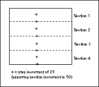
Figure 2 : Stepping Size
Follow section line
Select this option to follow an existing section line. The nominated line, which must be digitised or loaded prior to using this option, is a special line where increments are marked between selected points. For example, you may want to go 5 metres in one direction and at the end of this distance go 10 metres in another direction.
Shadow previous string
Select this check box to shadow and temporarily project the last string of the previous section onto the section plane as you move to the next section. This is particularly useful if you have much data and are trying to trace through an ore body.
Use crossing triangulation/trification check
Select this check box to check for crossing triangulations and trifications. You should use this option if you are planning on using the triangulation for volume or reserve calculations.
Cross triangulations
As the triangles are being built, they sometimes pass through and cross each other. If this occurs, a spatially corrupt solid will be built. Crossing triangulations can produce errors during other processes. Checking this check box will warn you if triangles cross and will offer the option of reversing the triangulation. This reversal switches the direction of the second string and in some instances is sufficient to uncross the solid. The reversal does not affect the direction of the original data in the object.
Trifications
Trifications (edges with three or more neighbouring triangles) will also result in spatially corrupt solids. Selecting this check box will warn you if trifications exist.
Refer to Model > Triangle Utility > Check for an explanation of the tests.
Note: We recommend that you perform and pass all test mentioned in the Check option before using any triangulation for volume or reserve calculations. Even very small gaps or inconsistencies, which may not be easily visible on the screen, can sometimes cause leakage or problems when measuring volumes.
Prompt to close open strings
Select this check box to be asked whether or not to close open strings when they are selected for triangulating. Open strings may affect future volume calculations.
Link to block model
Select this check box to evaluate the reserves while designing the model.
Solid shaded surface
Select this check box to display the new triangulations as solid shaded surfaces, that is, not transparent and no mesh lines. Use the 3D/Solid Shading icon on the Graphics toolbar to turn the shading on/off once the triangulation has been loaded.
Note: Solid shading requires additional memory.
Show triangles on shaded surface
Check this box to display the actual triangulation lines as well as the solid shading.
Click OK.
If you selected the Use automatic section increment check box, then the Plane Definition panel displays. Otherwise, if you chose to use tie strings, the Multiple Selection box displays. From this box, choose the method of selecting the tie strings and select the tie strings.
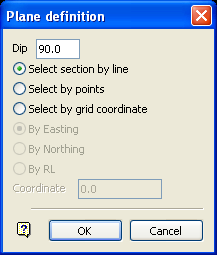
Plane Definition panel
Dip
The dip is the angle of the section from horizontal. Valid dip angles are between -90° and 90°.
Select section by line
Select this option to define the plane by selecting an existing line and specifying the dip.
Only design strings may be picked and it is not possible to pick a line in an underlay. The direction of the view, and therefore the direction of the stepping, depends on the digitised sequence of the line. The digitised sequence of the line can be reversed using the Design > Object Edit > Reverse option.
Select by points
Select this option to define the plane by digitising two points and specifying the dip.
To locate a point precisely, use the Snap to Objects or Snap to Points modes (on the Digitise toolbar). Points may be snapped onto underlays, such as block model slices or triangulations. If you use Indicate mode to select the points, then the points have the current default Z value.
Select by grid coordinate
Select this option to define the plane by using a specific grid coordinate. The grid co-ordinates can contain up to three decimal places. To achieve the best results for the following three methods, we recommend using the Zoom Data Extents icon (on the Graphics toolbar) in order to view all of the graphics.
- By Easting - Select this option to enter a specific Easting value (X value).
- By Northing - Select this option to enter a specific Northing value (Y value).
- By RL - Select this option to enter a specific RL value (Z value).
Select by 3 points
Select this option to define the plane by digitising 3 points. To locate a point precisely, use the Snap to Objects or Snap to Points modes (on the Digitise toolbar). Points may be snapped onto underlays, such as block model slices or triangulations.
Using this option will allow you to explicitly define the location and orientation of a plane by indicating 3 points. The first two points define the bearing of the plane, and the third point defines the dip of the plane.
Click OK.
![]() Note
Note
Using section increments does not stop you looking at the data in 3D. However, when you go back to selecting, it will return to the section on which you are working.
Select the strings/polygons to triangulate. At any time during the string selection, you can right-click to cancel and access the Create toolbar which contains picking preferences.
If you chose to build multiple triangulations, that is, you selected the Break solid by strings option, then you will be prompted for the name of the triangulation as well as the triangulation colour.
The Create toolbar is then displayed.
The displayed toolbar will allow you to change the picking method. The contents of the Create toolbar will change once an option has been selected and used, that is, a 3D Create section will be added.
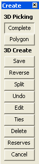
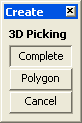
3D Create
Complete
Select this option to use all of the points on the next selected string to create the triangulation.
Polygon
Select this option of you want to digitise a polygon while building the solid. You will need to nominate the layer in which to store the polygon.
The following options will be displayed when an option has been selected from the Create toolbar.
3D Create
Save Select this option to save the triangulation. Once selected, the standard Triangulation Attributes panel will be displayed.
Refer to the Model > Triangle Utility > Attributes option for more information on this panel.
Reverse
Select this option to reverse the direction of the last selected string and then re-triangulate between the last two strings. This is to overcome any digitising problems and the 'direction' - either clockwise or anti-clockwise in which the strings were created. It only changes the direction of the points in the object, with respect to the triangulation, that is, the original string is unchanged. It can be used as a quick way to uncross crossed triangulations.
Split
Select this option to pause triangulating, to move to another string and then recommence triangulating. If you do this, you may have four or more 'gaps' that is, no end plates, on the triangulations. Take care to close the triangulation before using the Volume or Reserve options.
Undo
Select this option to remove, in reverse order, the sections of the triangulation.
Edit
Select this option to insert, delete, move or filter points or delete strings. Filtering points removes excess points without altering the shape of the string. Refer to the Design > Object Edit > Filter option for a detailed explanation.
Ties
Select this option to digitise ties as you triangulate. The default digitising mode is Snap to Points ![]() . If you select a string and create a triangulation that is not correct, then you can undo it, enter the ties and continue to triangulate.
. If you select a string and create a triangulation that is not correct, then you can undo it, enter the ties and continue to triangulate.
Delete
Select this option to delete a selected polygon.
Reserves
Select this option to evaluate reserves on the last string or all strings of the model being created. The reserves panels will then be displayed as per the General option (under Block > Reserves ).
Cancel
Select this option to exit the option. You will be prompted as to whether or not you want to save the changes.

