Adjustments
Perform Standard Survey Adjustments
The Adjustments option to perform at least squares network adjustment of a survey network or a Bowditch adjustment of a graphical object representing a traverse survey. These adjustments can be performed in either 2D or 3D.
- Least Squares
This method gathers observation data, performs the survey network adjustment, displays the observations graphically, and writes a report to the current working directory. The format of the report file name is<object>.lsa_list. An example is given in Appendix A. - Bowditch
This method takes a graphical object representing a traverse of some kind and performs a Bowditch adjustment, generating an additional graphical object representing the adjusted traverse, with a detailed report. The format of the report file name is<object>.bow_list. An example is given in Appendix A.
Instructions
- Select Survey menu
- Select Surveying submenu
- Select Adjustments option
Select either the Least Squares or Bowditch method.
Least Squares Adjustment
This option allows easy entry of all the observations required to do a Least Squares Network Adjustment. Users enter their fixed stations (control stations), their observations (angles and distances), then their free stations (the stations that are to be adjusted by the program), and these are combined into an observations file, which is the input for the external Least Squares Adjustment program. The adjustment uses the variation of coordinates least squares approach, which requires approximate coordinates for the free stations to be included. Then this adjustment program is run and the results displayed.
A graphical representation of the network displays, showing all observations and stations in the adjustment. You can go back and edit or append observations at any time in the future through the panels or using an editor on the <object>.lsa_dat file.
When you select the Least Squares Adjustment method, the following panel displays.
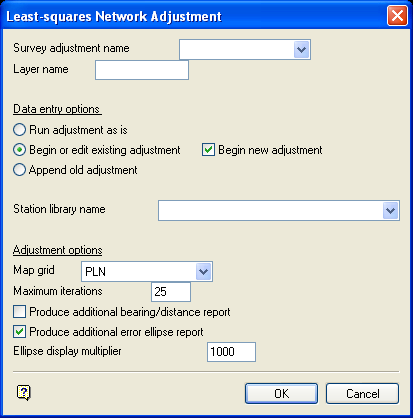
Least-squares Network Adjustment panel
Survey adjustment name
Enter the name for the adjustment (a maximum of 10 alphanumeric characters) The specified name will be used for future editing of the observations. If the name already exists, then you will be prompted, upon completion of the panel whether or not to overwrite the name.
Layer name
Enter the layer name. The layer name can contain up to 40 alphanumeric characters (spaces are not allowed).
Data entry options
Run adjustment without data entry
Select this check box if no editing is required. The adjustment will run and display the results. All other data entry and adjustment options will be shadowed, that is, cannot be selected.
Begin new adjustment
Select this option to start with new observational data.
Edit/append old adjustment
Select this option to edit and append data.
Append old adjustment
Select this option if you are satisfied with the existing data and only want to append new observations to the adjustment. This saves scrolling through multiple panels of observations if you only want to append to the end of the observations.
Station library name
This defines the library name used to supply the default coordinates for the stations in the adjustment.
Adjustment options
Map grid
Enter, or select from the drop-down list, the survey grid that will define how the adjustment is to be done. Adjustment method PLN will be performed on a plane, adjustment methods AMG, ISD and MGA will be performed on its respective grid, that is, scale all distances by the line scale factor and apply the arc-chord corrections to bearings. In this case, entered distances are assumed spheroidal.
Maximum iterations
This defines the maximum number of iterations allowed in the adjustment. The default is 25 and normally the adjustment will converge before this number of iterations has been reached.
Produce additional bearing/distance report
Select this check box to produce a report of the calculated forward and back bearings and distances between all stations in the network. For UTM adjustments, bearings will be grid bearings and all distances spheroidal. The report will be appended to the <object>.lsa_list report.
Produce additional error ellipse report
Select this check box to produce a report of the error ellipse at each free station based on a 95% confidence interval. Additionally, the ellipses are displayed graphically. To facilitate this latter point, an Ellipse display multiplier is required to enable the ellipses to be seen (they are normally very small in relation to the size of the network). The report will be appended to the <object>.lsa_list report.
Select OK
Once you have completed the panel, the following panel is then displayed.
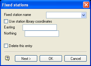
Fixed stations panel
Enter all fixed stations, using the Next/Back buttons to move through the fixed stations for editing and viewing.
Important: Do not select OK until all fixed stations have been entered as doing so will cause the Adjustment option to assume that all remaining items contains their current values.
Example: If you have 100 fixed stations, and want to edit the 20th station, then use the Next button to move through the available stations. After reaching the 20th station, and making the required edits, select OK if you want the remaining stations to retain their current values.
If Use station library coordinates is checked, and the station exists in the chosen station library, then its coordinates are extracted from the library. Otherwise, enter the coordinates manually.
Once all fixed stations have been entered, select OK. Once selected, the following panel displays. This panel will allow you to enter the angle and distance observations.
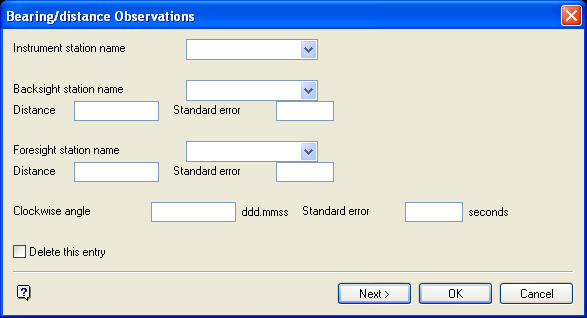
Bearing/distance Observations panel
The observations that may be entered are:
- The clockwise angle measured at the instrument station from the backsight to the foresight, plus its standard error in seconds.
- The distance from the instrument station to the backsight, along with its standard error in units For example, 5 mm in a metres window would be entered as 0.005.
- The distance from the instrument station to the foresight, along with its standard error.
All three of these observations are optional. Complete only those panel fields necessary to define the observation. As before, use the Next/Back buttons to move through the entered observations.
Once all observations have been entered, select OK.
Upon selection, you will be asked whether to edit new free stations only or all free stations. Upon confirmation the program determines all the free station names, that is, all stations included in the observations, but not in the entered fixed stations. In a panel identical to the fixed station panel, enter the approximate coordinates of the free stations.
If using the Append data entry options, you are given the option of editing all the fixed stations or any new fixed stations used in the appended observations. If Edit all free stations is selected, the following panel displays.
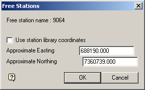
Free Stations panel
The Use station library coordinates check box need only be checked if the coordinates are not in the station library.
When accepting the panel, the formatted observations for the station are displayed on the screen. Cancel to display the panel for the next free station. Once all have been processed, Cancel again.
You are then asked whether you want to continue with the adjustment or quit the run. If you quit, entered observations will be saved, but will not be run. If you continue, the adjustment is run and, if successful, a report is generated and displayed in a separate window. On cancelling out of the window, a graphical display of the network appears, showing lines along which observations were made and all fixed and free stations. If the error ellipse option was used, error ellipses appear around all free stations.
After the adjustment has been completed successfully, use the Analyse > Label > Object Label option on the graphic representation of the traverse. This displays the traverse line numbers and whether the survey lines were fixed or free for adjustment. The Analyse > Label > Point Label option displays the survey station names.
Use the  Information button on the Status toolbar to display the layer name, object name on each traverse line and whether the line was determined using angle or angle and distance. Using the Information button on each traverse station displays whether the station was fixed or free in the adjustment.
Note: If the adjustment is unsuccessful, a message "Error running adjustment program!" will appear. Clicking OK or CANCEL displays a listing, giving the error that occurred.
For more information on the Least Squares Network Adjustment program, see Appendix B.
Bowditch Adjustment
This method is popular for the average type of engineering survey due to its ease in application and the fact that corrections, although affecting the bearings of the lines, do not affect the plotting to a noticeable extent
The Bowditch adjustment option takes an existing graphical object representing a traverse and adjusts it based on the Bowditch method:
Upon selection of the method you are prompted to select the traverse object to adjust from a loaded layer. This may have come from a data collector download, or may have been digitised, etc. Any object can be selected. The ordering of points in the selected object determines the direction of the traverse. The point names of the object should represent the names of the traverse stations.
The following panel is then displayed.
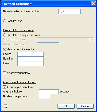
Bowditch Adjustment panel
Name for adjusted traverse object
The maximum size is 10 alphanumeric characters. The default is the name of the selected object. The layer into which the new adjusted object is placed is that of the unadjusted object.
Loop traverse
Selection of this option assumes that the traverse is to close onto the starting point.
Use station library coordinates
Selection of this option assumes that the traverse is too close to one of the stations in the survey station library. Both the Station library name and the Closing station name must be entered.
Manual coordinate entry
Selection of this option requires the Easting and Northing of the traverse closing point to be entered.
Adjust level misclose
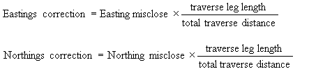
If you check this box then any level misclose in the traverse will be distributed over all the stations in the traverse. The level misclose adjustment calculation method is identical to that of the eastings and northings misclose adjustment method used by Bowditch, that is,
Level correction = Level misclose * (traverse leg length/total traverse distance)
Angular misclose adjustment
Select this check box to correct any angular misclose that may have been measured. Enter the Angular misclose in seconds. The Number of angles read is by default the number of legs in the traverse. This should be altered to reflect the number of angles actually read in the traverse. The angular misclose adjustment is done in the standard way, dividing the misclose by the number of angles read and distributing this proportionally to each traverse leg.
Select OK
To accept the panel. Once the panel is accepted, the Bowditch adjustment listing displays on the screen. The first section shows the original coordinates with calculated bearings and distances based on these coordinates If the angular misclose is being adjusted, the bearings will reflect this adjustment, which is done prior to the standard Bowditch adjustment. The second section shows the result of the adjustment. The adjusted bearings and distances are based on the adjusted coordinates.

