Extents
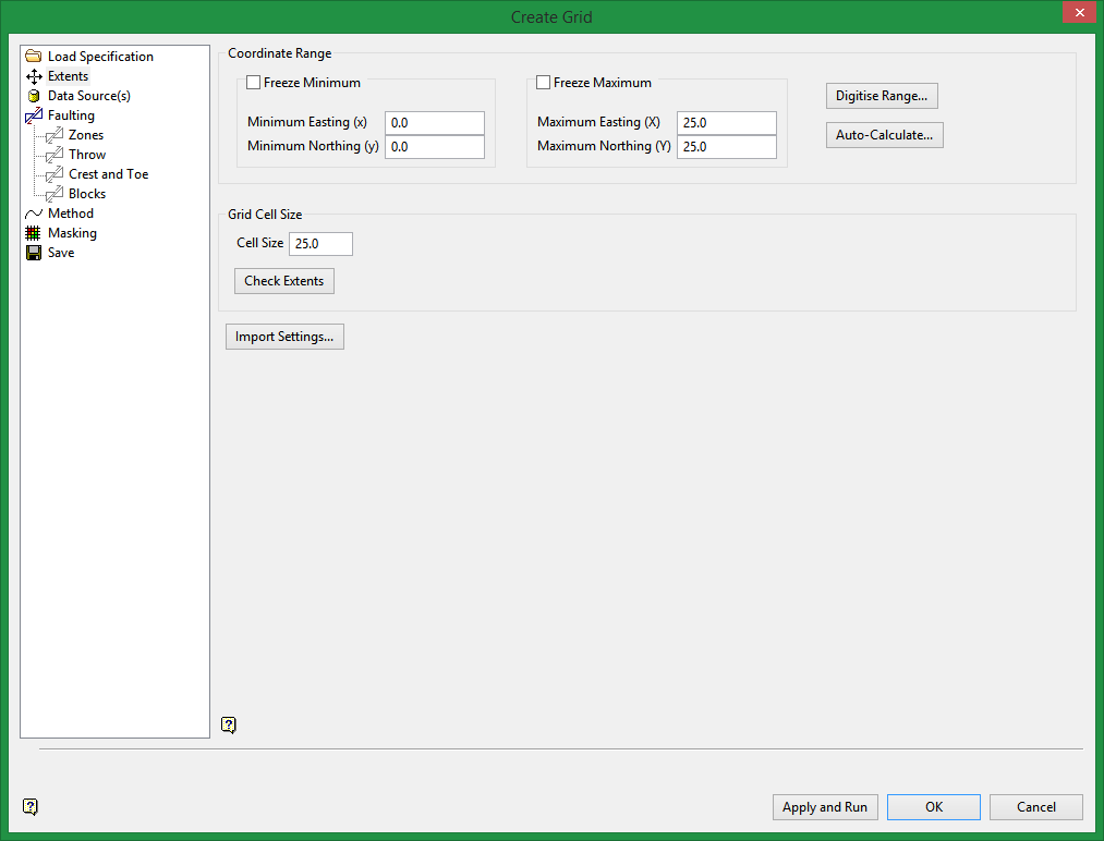
Coordinate Range
Specify the values for the minimum and maximum Eastings and Northings. These values define the four corners of every grid created using these specifications.
Note: The grid(s) cell size must divide evenly into the Easting and Northing extents of the area.
Freeze Minimum / Freeze Maximum
Select the Freeze Minimum or Freeze Maximum check box if you want the minimum or maximum extents to stay the same when the extents are recalculated.
Cell Size
Enter the Cell Size. After you enter a cell size and click Check Extents, the number of points that will make up the grid is re-calculated and displayed to the right of the box.
Check Extents
Click the Check Extents button to re-calculate extents.
Digitize Range
Click Digitize Range if you want to dynamically digitise the extents. Click on the desired minimum and maximum values to digitise the extents. When you return to the interface, the minimum and maximum fields contains the appropriate values.
Auto-Calculate
Note: To view the current extents, click Digitize Range. Once selected, the interface will "collapse" and the current extents will be displayed. Right-click to return to the interface.
Click Auto-Calculate if you want to use an existing drillhole database to calculate the X and Y extents. Once selected, the Auto Calculate Model Extents panel will be displayed.
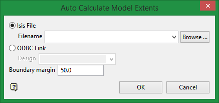
Select a drillhole database and specify the border margin. The drop-down list displays all drillhole database found within your current working directory.
Click OK to return to the interface.
Enter the default grid cell size. As a general rule, one-fifth of the average data spacing is a suitable size. While there are no software limits on the number of cells within a grid, obviously speed of operation may suffer when using a large numbers of cells. Grid cell size values can contain a single decimal place.
Import Settings
Click Import Settings if you want to use the settings contained within another file. Once selected, the Import Model Extents panel is displayed.
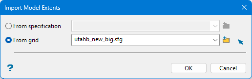
Specify the name of the specification file that contains the desired settings. The drop-down list displays all .gdc_spec, .fd_spec, .sme_spec and .cms_spec files found within your current working directory. Click Browse to select a file from another location.
Select the grid file (.sfg) from the drop-down list. The drop-down list displays all grid files found within your current working directory. Click Browse to select a file from another location.
Click OK to return to the interface.
Note: If desurvey information is available, it is used by default when generating grid surfaces using this tool.
Related topics

