Design
The Design group of the Charging ribbon contains tools to create and edit charge rules and tie-ups.
Create Charge Rule
A charge rule is a JavaScript snippet which defines the location, quantity and types of products you plan to insert into each hole in a blast. The aim of the charge rule is to fill the hole with particular products using the following information:
-
The charge rule parameters
-
The hole length and geometry
-
The blast product catalogue
When you apply a charge rule to a set of holes, BlastLogic automatically creates a charge sheet which operators can access on the tablet. Prior to confirming the application of a charge rule, BlastLogic will display a charge plan preview. This will contain information in a tabular format, as well as a 2D hole view for the selected hole. After you successfully apply a charge rule, BlastLogic will automatically publish the rule for future use.
Selecting the create charge rule tool
To select the tool, you can use either of the following methods:
-
On the Charging ribbon, in the Design group, select Create Charge Rule. In the drop-down menu, you can select from either a
 Blank or an
  Assisted charge rule.
 -
Alternatively, you can right click on a blast charge rules container in the data explorer and select Create Charge Rule from the context menu. You can then select from either a Blank charge rule... or an Assisted charge rule....
Either of the following panels will appear:
-
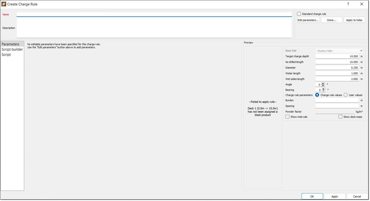
Blank Create Charge Rule panel
![]()
-
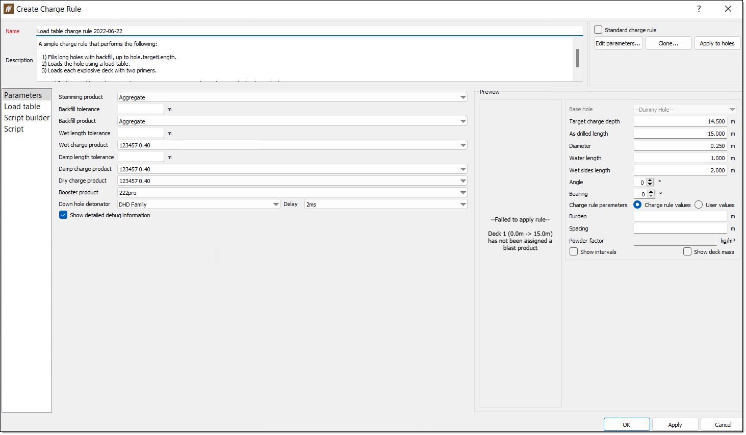
Assisted Create Charge Rule panel
Creating a charge rule
There are two ways to create a charge rule in BlastLogic. A blank charge rule allows you to create a charge rule from scratch. Alternatively, an assisted charge rule provides you with options which BlastLogic uses to build the charge rule. Navigate to the desired method by selecting a link below:
Blank
To create a blank charge rule, follow these steps:
-
On the Charging ribbon, in the Design group, select Create Charge Rule > Blank. The Create Charge Rule panel will appear.
-
Enter the desired information into the Name and Description fields.
Tip!BlastLogic will use the name you enter to uniquely identify the charge rule. The name must be different from all other existing charge rules. Using a naming convention when you create charge rules will make it easier to find them later.
-
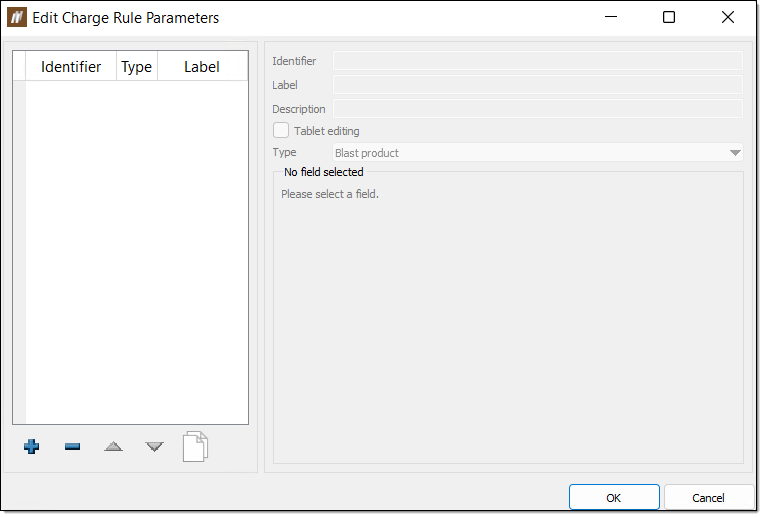
Select Edit parameters.... The Edit Charge Rule Parameters panel will appear.
-
Click
 to add a new parameter. BlastLogic will give the new parameter default names in the Identifier and Label fields.
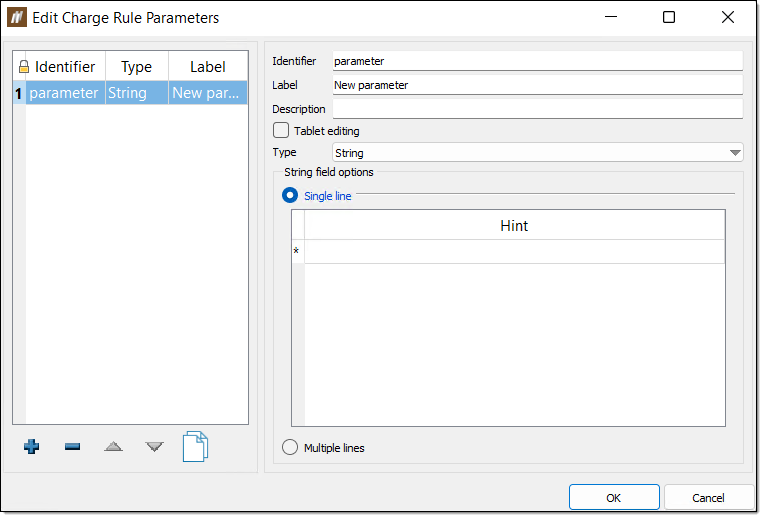
-
Enter the desired information into the Identifier, Label and Description fields.
-
Select the Tablet editing checkbox to allow operators to edit the charge rule on the tablet.
-
Select the property type using the Type drop-down. There are nine types to choose from in BlastLogic:
-
Blast product — These types are contain information on blast products which you can use to fill holes.
-
Blast product family — These types contain information on a group of blast products. This group is known as a blast product family and typically contains a set of one product with varying densities.
- Boolean — You can turn these types on or off via a checkbox.
-
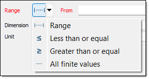
Float — These types must have a range set as greater than a given value, less than a given value, in between two values, or all values. You must also define the dimension and units of float types.
-
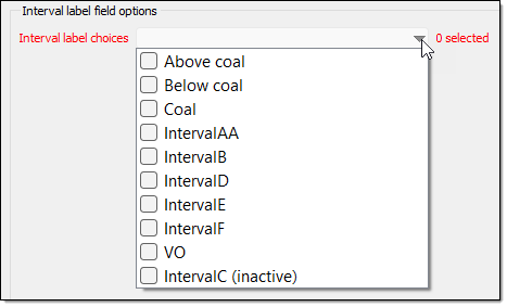
Interval label — These types contain the interval labels you wish to include in the rule.
-
Load table — These types add load tables to the rule. Load tables allow you to set load designs in tabular form.
-
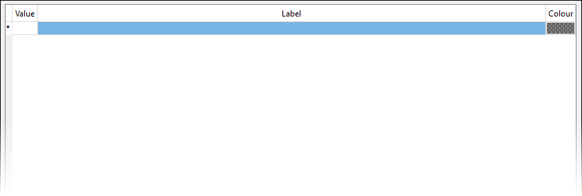
Select — These fields display a table, in which you can enter each possible value for the field. These values will be shown in a drop-down list for the field and you can only select one value at a time.
-
Multi-select — These fields are the same as select fields, except you can select multiple values from the drop-down list.
-
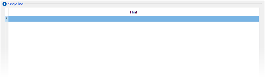
String — These types can be either a single line or a multiple line string. Single line strings can have one or more hints to store commonly entered values.
-
-
Specify the additional options. You can also set the following fields, depending on the selected type:
-
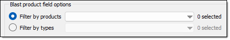
Blast product field options — Set the product(s) by filtering using the Filter by products or Filter by types radio buttons and drop-downs.
-
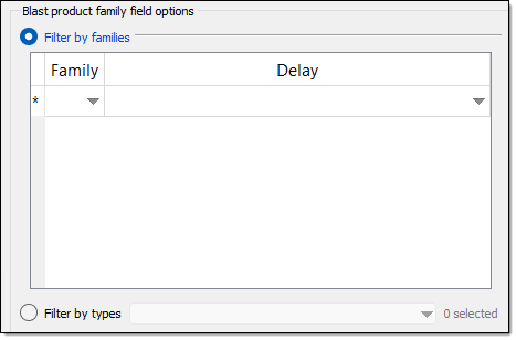
Blast product family — Set the product family by filtering using the Filter by families or Filter by types radio buttons and drop-downs. To filter by families, enter the desired family and delay using the Family and Delay columns and drop-downs.
-
Range — Set the range of the parameter by selecting how you wish to define the range and entering the desired values.
-
Dimension — Set the dimension using the corresponding drop-down.
-
Unit — Set the units using the corresponding drop-down.
-
Interval label field options — Set the label for the interval using the Interval label choices drop-down.
-
Value — Set the label and colour associated with a particular value.
-
Hint — Set commonly entered values.
Optionally, select the Multiple lines radio button for a multiple line string. You cannot define hints for this option.
-
-
Optionally, use the following actions to edit the parameters:
-
To remove a parameter, select the parameter and click
 .
. -
To clone a parameter, select the parameter and click
 .
. -
To reorder the parameters, select the parameter you wish to move and click the
 and
and  arrows.
-
-
After adding the desired parameters, click OK.
-
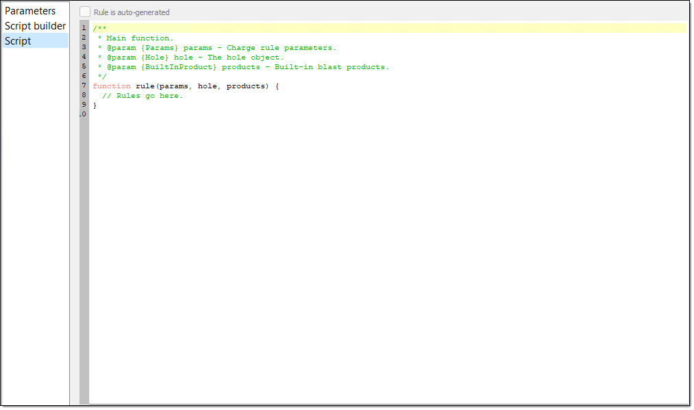
Select the Script tab in the Create Charge Rule panel.
-
Fill out the charge rule script in the Script tab, using the JavaScript programming language. The script is responsible for calculating a set of decks that completely fill the hole with desired blast products.
-
Save the new charge rule by clicking OK or Apply.
Note:The new charge rule does not exist in the database until you save it for the first time. If you decide you don't want to save the new charge rule, click Cancel.
Assisted
To create an assisted charge rule, follow these steps:
-
On the Charging ribbon, in the Design group, select Create Charge Rule > Assisted.
The Create Charge Rule panel will appear. BlastLogic will automatically fill the Name and Description fields and add the Load tables tab to the panel. By default, the backfilling of short holes option is also pre-selected in the Script builder tab.
-
Optionally, provide the rule with a custom name and description using the Name and Description fields.
Tip!BlastLogic will use the name you enter to uniquely identify the charge rule. The name must be different from all other existing charge rules. Using a naming convention when you create charge rules will make it easier to find them later.
-
Optionally, add extra parameters. Select Edit parameters... and add the desired parameters by clicking
and configuring the fields on the right hand site of the Edit Charge Rule Parameters panel. Expand for more information on the parameters options
To configure a new parameter, follow these steps:
-
Enter the desired information into the Identifier, Label and Description fields.
-
Select the Tablet editing checkbox to allow operators to edit the charge rule on the tablet.
-
Select the property type using the Type drop-down. There are nine types to choose from in BlastLogic:
-
Blast product — These types are contain information on blast products which you can use to fill holes.
-
Blast product family — These types contain information on a group of blast products. This group is known as a blast product family and typically contains a set of one product with varying densities.
- Boolean — You can turn these types on or off via a checkbox.
-
Float — These types must have a range set as greater than a given value, less than a given value, in between two values, or all values. You must also define the dimension and units of float types.
-
Interval label — These types contain the interval labels you wish to include in the rule.
-
Load table — These types add load tables to the rule. Load tables allow you to set load designs in tabular form.
-
Select — These fields display a table, in which you can enter each possible value for the field. These values will be shown in a drop-down list for the field and you can only select one value at a time.
-
Multi-select — These fields are the same as select fields, except you can select multiple values from the drop-down list.
-
String — These types can be either a single line or a multiple line string. Single line strings can have one or more hints to store commonly entered values.
-
-
Specify the additional options. You can also set the following fields, depending on the selected type:
-
Blast product field options — Set the product(s) by filtering using the Filter by products or Filter by types radio buttons and drop-downs.
-
Blast product family — Set the product family by filtering using the Filter by families or Filter by types radio buttons and drop-downs. To filter by families, enter the desired family and delay using the Family and Delay columns and drop-downs.
-
Range — Set the range of the parameter by selecting how you wish to define the range and entering the desired values.
-
Dimension — Set the dimension using the corresponding drop-down.
-
Unit — Set the units using the corresponding drop-down.
-
Interval label field options — Set the label for the interval using the Interval label choices drop-down.
-
Value — Set the label and colour associated with a particular value.
-
Hint — Set commonly entered values.
Optionally, select the Multiple lines radio button for a multiple line string. You cannot define hints for this option.
-
-
Optionally, use the following actions to edit the parameters:
-
To remove a parameter, select the parameter and click
. -
To clone a parameter, select the parameter and click
. -
To reorder the parameters, select the parameter you wish to move and click the
and arrows. -
To edit a pre-existing parameter, select the parameter and edit the fields on the right hand side of the panel.
-
-
After adding the desired parameters, click OK.
-
-
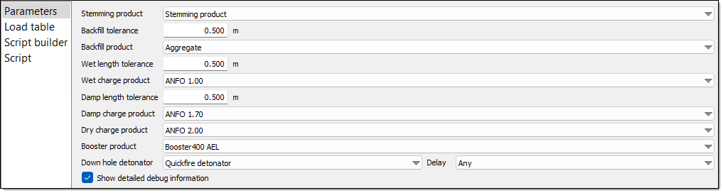
Optionally, edit the parameter values. BlastLogic pre-fills each parameter field in the Parameter tab. You can edit these values using the corresponding drop-downs.
-
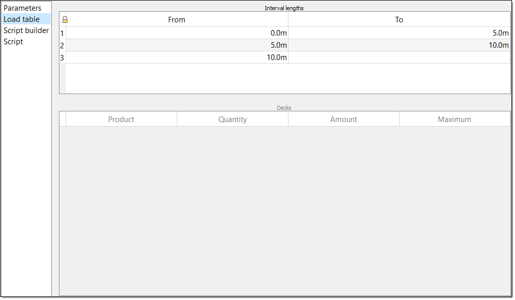
Select the Load table tab from the left side bar. Load tables allow you to fill holes based on their charge depths.
There are two tables in the load tables tab: the Interval lengths table and the Decks table. Each row in the Interval lengths table defines a range of hole lengths via the From and To columns. Each row also has an associated list of decks that are applied to the hole if the length of the hole falls within range. You can define these decks in the Decks table.
Note:This tab will only appear if you have defined a load table parameter in the Parameters tab. To add a load table, select Edit parameters... and click
to add a new parameter. Enter the appropriate information into the parameter fields and select Load table from the Type drop-down. Click OK to save the parameter.If you are not using a load table, proceed to step 8.
-
Enter the desired length intervals into the Interval lengths table. You can define the interval boundaries using the From and To columns. The last row of this table always has a blank To value as BlastLogic applies it to all the remaining holes with a length greater than or equal to the From value of that row.
-
Specify the decks for each interval by selecting the interval and adding the desired information into the Decks table. This table contains the following fill method headings:
-
Product — The type of product you wish to add.
-
Quantity — The quantity of the product you wish to add.
-
Amount — The amount of the product you wish to add.
-
Maximum — The maximum length of the deck you wish to use.
There are six different ways to specify the size of a deck:
-
Fixed length — The deck is always a specified length in the hole, with the length given in metres. The sum of all fixed length decks must not exceed the minimum length specified in the Interval lengths table.
-
Fixed volume — The deck always takes up a specified volume in the hole. BlastLogic calculates the length of this deck based on the diameter of the hole when you apply the charge rule. The volume is specified in cubic metres.
-
Fixed mass - The deck will always be a specified mass, given in kilograms. BlastLogicautomatically calculates the length of the deck based on the density of the chosen blast product and the diameter of the hole when you apply the charge rule. This option is not available for products with an undefined density.
-
Length above water — The top of this deck will extend to the specified distance above the wet part of the hole, given in metres. By default, the length above water decks will use the wet-sides measurement of the hole as the reference water level. However, a charge rule script can choose to calculate its own value to use as this water level.
The length above water decks also contain the following functionality:
-
You cannot place length above water decks on top of variable length decks.
-
If the hole is dry then BlastLogic will exclude this deck from the resulting charge plan.
-
BlastLogic will reduce the length of the deck if either of the following occur:
-
There is insufficient space remaining in the hole.
-
The blast product is explosive and the target explosive mass has been reached.
-
-
-
Target powder factor — The deck will always be specified by meeting a target powder factor, determined by the products density and the current hole diameter. This value is on a per deck basis, independent of any other explosive deck. This option is only applicable for explosive decks with a valid density.
-
Variable ratio — The ratio of the deck to be filled with the specified product. Ratio values for non-explosive decks are considered ratios of length, whereas ratio values for explosive decks are considered ratios of mass.
Note:Variable length decks can optionally use the Maximum column. This column defines the maximum length of a given deck. The remainder of the hole should be covered by other deck options as specified above, including at least one Variable length deck with no maximum.
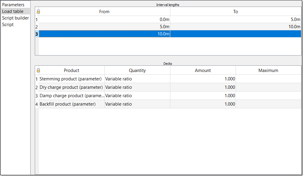
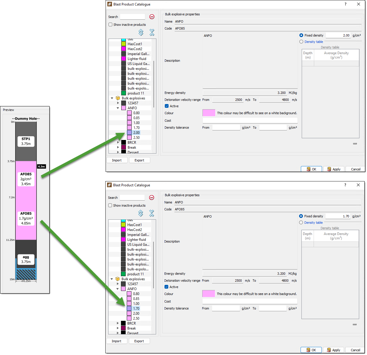
In the screenshot above, the Quantity column is set to Variable ratio with the Amount values column set to 1.000. This corresponds to each product having a variable mass ratio of 1:1 in the hole. You can view this in the 2D hole preview.
In this view, you can see that BlastLogic has increased the amount of AFO85, due to its lower density. You can view the densities of each material in the blast product catalogue. To open this catalogue, navigate to the Home ribbon, in the Setup group and select Blast Product Catalogue. For more information on this catalogue, refer to the Blast product catalogue section of the setup page.
-
-
Review the Script builder tab. After you fill in the load table, BlastLogic creates a simple script in the Script builder tab. In this tab, you can view and edit the pre-selected options to generate a new script if you desire. Alternatively, you can fill out the charge rule script manually in the Script tab, using the JavaScript programming language. The script is responsible for calculating a set of decks that completely fill the hole with desired blast products.
-
Save the new charge rule by clicking OK or Apply.
Note:The new charge rule does not exist in the database until you save it for the first time. If you decide you don't want to save the new charge rule, click Cancel.
Loading a charge rule
To load a charge rule from the server, refer to the Load charge rule or Load charge rule from holes sections on the load page.
Cloning an existing charge rule
After publishing a charge rule, you can only modify its name and description. BlastLogic prevents further editing to preserve the charge rule settings for historical accuracy.
To make changes to an existing charge rule, you must make an editable copy of the charge rule by cloning it. The cloned charge rule contains all of the same information, parameters and rules as the original copy, but you can modify all aspects of it.
To clone a charge rule, follow these steps:
-
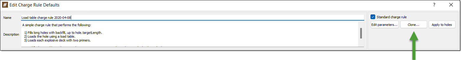
In the charge rules container, in the data explorer, double click on the charge rule you wish to change. The Edit Charge Rule Defaults panel will appear.
-
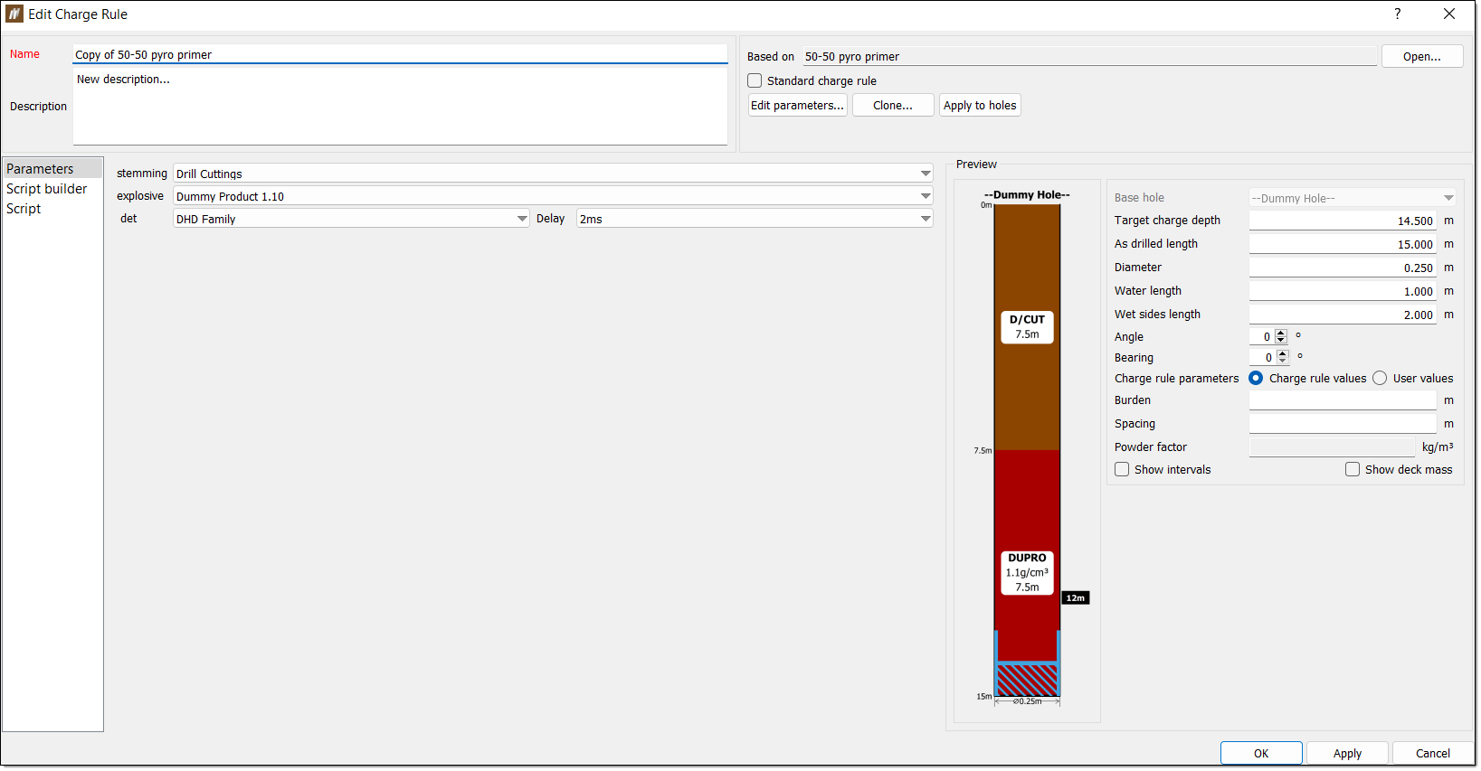
Select Clone.... BlastLogic will display the same panel but with a cloned version of the charge rule, named Copy of <charge rule name>.
 Note:
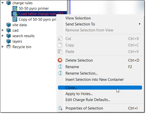
Note:Alternatively, clone a charge rule by right clicking on the charge rule, located in the charge rules container in the data explorer, and select Clone from the context menu.
Edit Charge Rule
The Edit Charge Rule tool allows you to edit charge rules and add charge products to multiple holes. When editing a charge rule, it is important to note whether the charge rule is published or unpublished. You can make the following edits based on each type:
-
For a published charge rule, you can only edit specific properties such as the Name and Description fields. BlastLogic only allows these changes to preserve the rule. If you wish to edit a published charge rule, you can clone it which creates a cloned version. To do this, refer to the Cloning an existing charge rule section of the design page.
-
For an unpublished charge rule, you can edit any of the tabs or fields.
To edit a charge rule, follow these steps:
-
Select the charge rule you wish to edit from the charge rules container, in the data explorer.
-
On the Charging ribbon, in the Design group, select Edit Charge Rule. Alternatively, you can right-click on the charge rule in the data explorer and select Edit Charge Rule... from the context menu.
The Edit Charge Rule panel will appear.
-
Edit the charge rule. BlastLogic provides you with the following four tabs which you can edit:
Parameters
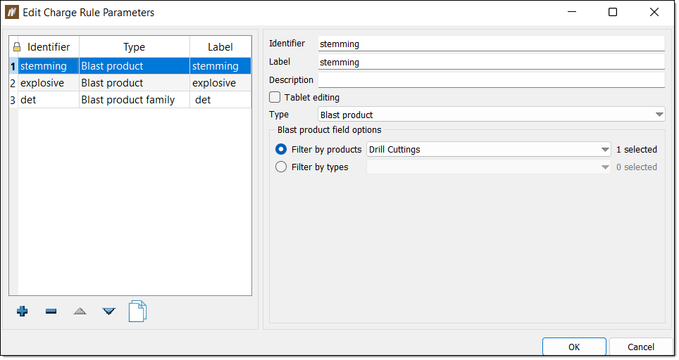
The Parameters tab allows you to set blast products as general parameters. This is important as setting these products as parameters allows you to access them in the charge rule script via the params objects.
To edit the charge rule parameters, follow these steps:
-
Select Edit parameters... from the Edit Charge Rule panel. The Edit Charge Rule Parameters panel will appear.
-
Make the desired changes to the parameters by adding parameters, removing parameters or editing the parameter properties.
Expand for detailed instructions on editing this tab.
Use the following options to make the desired edits to the charge rule parameters:
-
To add a new parameter, select
. -
To remove a parameter, select the parameter and click
. -
To clone a parameter, select the parameter and click
. -
To reorder the parameters, select the parameter you wish to move and click the
and arrows.
-
To edit a parameter, follow these steps:
-
Select the parameter in the left hand side table.
-
Edit the information in the Identifier, Label and Description fields as desired.
-
Select or clear the Tablet editing checkbox to allow or prevent modifications being made to the charge rule on the tablet.
-
Select a different property type using the Type drop-down. There are nine types to choose from in BlastLogic:
-
Blast product — These types are contain information on blast products which you can use to fill holes.
-
Blast product family — These types contain information on a group of blast products. This group is known as a blast product family and typically contains a set of one product with varying densities.
- Boolean — You can turn these types on or off via a checkbox.
-
Float — These types must have a range set as greater than a given value, less than a given value, in between two values, or all values. You must also define the dimension and units of float types.
-
Interval label — These types contain the interval labels you wish to include in the rule.
-
Load table — These types add load tables to the rule. Load tables allow you to set load designs in tabular form.
-
Select — These fields display a table, in which you can enter each possible value for the field. These values will be shown in a drop-down list for the field and you can only select one value at a time.
-
Multi-select — These fields are the same as select fields, except you can select multiple values from the drop-down list.
-
String — These types can be either a single line or a multiple line string. Single line strings can have one or more hints to store commonly entered values.
-
-
Edit any additional options. You can also edit the following fields, depending on the selected type:
-
Blast product field options — Set the product(s) by filtering using the Filter by products or Filter by types radio buttons and drop-downs.
-
Blast product family — Set the product family by filtering using the Filter by families or Filter by types radio buttons and drop-downs. To filter by families, enter the desired family and delay using the Family and Delay columns and drop-downs.
-
Range — Set the range of the parameter by selecting how you wish to define the range and entering the desired values.
-
Dimension — Set the dimension using the corresponding drop-down.
-
Unit — Set the units using the corresponding drop-down.
-
Interval label field options — Set the label for the interval using the Interval label choices drop-down.
-
Value — Set the label and colour associated with a particular value.
-
Hint — Set commonly entered values.
Optionally, select the Multiple lines radio button for a multiple line string. You cannot define hints for this option.
-
-
-
-
Click OK to save the edits. BlastLogic will update the Preview section and the Parameters tab of the Edit Charge Rule panel.
Load table
The Load table tab allows you to create load tables which let you fill holes based on their charge depths.
Note:This tab will only appear if you have defined a load table parameter in the Parameters tab. To add a load table, select Edit parameters... and click
to add a new parameter. Enter the appropriate information into the parameter fields and select Load table from the Type drop-down. Click OK to save the parameter.To edit a load table, follow these steps:
-
Select the Load table tab. This label may vary as BlastLogic names this tab after the name you provided in the Label field when creating the parameter. The load table information will appear in the panel.
-
Make the desired edits to the load table by altering the interval lengths or associated decks.
Expand for detailed instructions on editing this tab.
There are two tables in the load tables tab:
-
The Interval lengths table
-
The Decks table
Each row in the Interval lengths table defines a range of hole lengths via the From and To columns. Each row also has an associated list of decks that are applied to the hole if the length of the hole falls within range. You can define these decks in the Decks table.
Note:This tab will only appear if you have defined a load table parameter in the Parameters tab. To add a load table, select Edit parameters... and click
to add a new parameter. Enter the appropriate information into the parameter fields and select Load table from the Type drop-down. Click OK to save the parameter.Follow these steps to make the desired edits to the load tables tab:
-
Edit the desired length intervals in the Interval lengths table. You can define the interval boundaries using the From and To columns. The last row of this table always has a blank To value as BlastLogic applies it to all the remaining holes with a length greater than or equal to the From value of that row.
-
Edit the decks for each interval by selecting the interval and adding the desired information into the Decks table. This table contains the following fill method headings:
-
Product — The type of product you wish to add.
-
Quantity — The quantity of the product you wish to add.
-
Amount — The amount of the product you wish to add.
-
Maximum — The maximum length of the deck you wish to use.
There are six different ways to specify the size of a deck:
-
Fixed length — The deck is always a specified length in the hole, with the length given in metres. The sum of all fixed length decks must not exceed the minimum length specified in the Interval lengths table.
-
Fixed volume — The deck always takes up a specified volume in the hole. BlastLogic calculates the length of this deck based on the diameter of the hole when you apply the charge rule. The volume is specified in cubic metres.
-
Fixed mass - The deck will always be a specified mass, given in kilograms. BlastLogicautomatically calculates the length of the deck based on the density of the chosen blast product and the diameter of the hole when you apply the charge rule. This option is not available for products with an undefined density.
-
Length above water — The top of this deck will extend to the specified distance above the wet part of the hole, given in metres. By default, the length above water decks will use the wet-sides measurement of the hole as the reference water level. However, a charge rule script can choose to calculate its own value to use as this water level.
The length above water decks also contain the following functionality:
-
You cannot place length above water decks on top of variable length decks.
-
If the hole is dry then BlastLogic will exclude this deck from the resulting charge plan.
-
BlastLogic will reduce the length of the deck if either of the following occur:
-
There is insufficient space remaining in the hole.
-
The blast product is explosive and the target explosive mass has been reached.
-
-
-
Target powder factor — The deck will always be specified by meeting a target powder factor, determined by the products density and the current hole diameter. This value is on a per deck basis, independent of any other explosive deck. This option is only applicable for explosive decks with a valid density.
-
Variable ratio — The ratio of the deck to be filled with the specified product. Ratio values for non-explosive decks are considered ratios of length, whereas ratio values for explosive decks are considered ratios of mass.
Note: Variable length decks can optionally use the Maximum column. This column defines the maximum length of a given deck. The remainder of the hole should be covered by other deck options as specified above, including at least one Variable length deck with no maximum.
-
-
-
Review the Preview section to check the edits.
Script builder
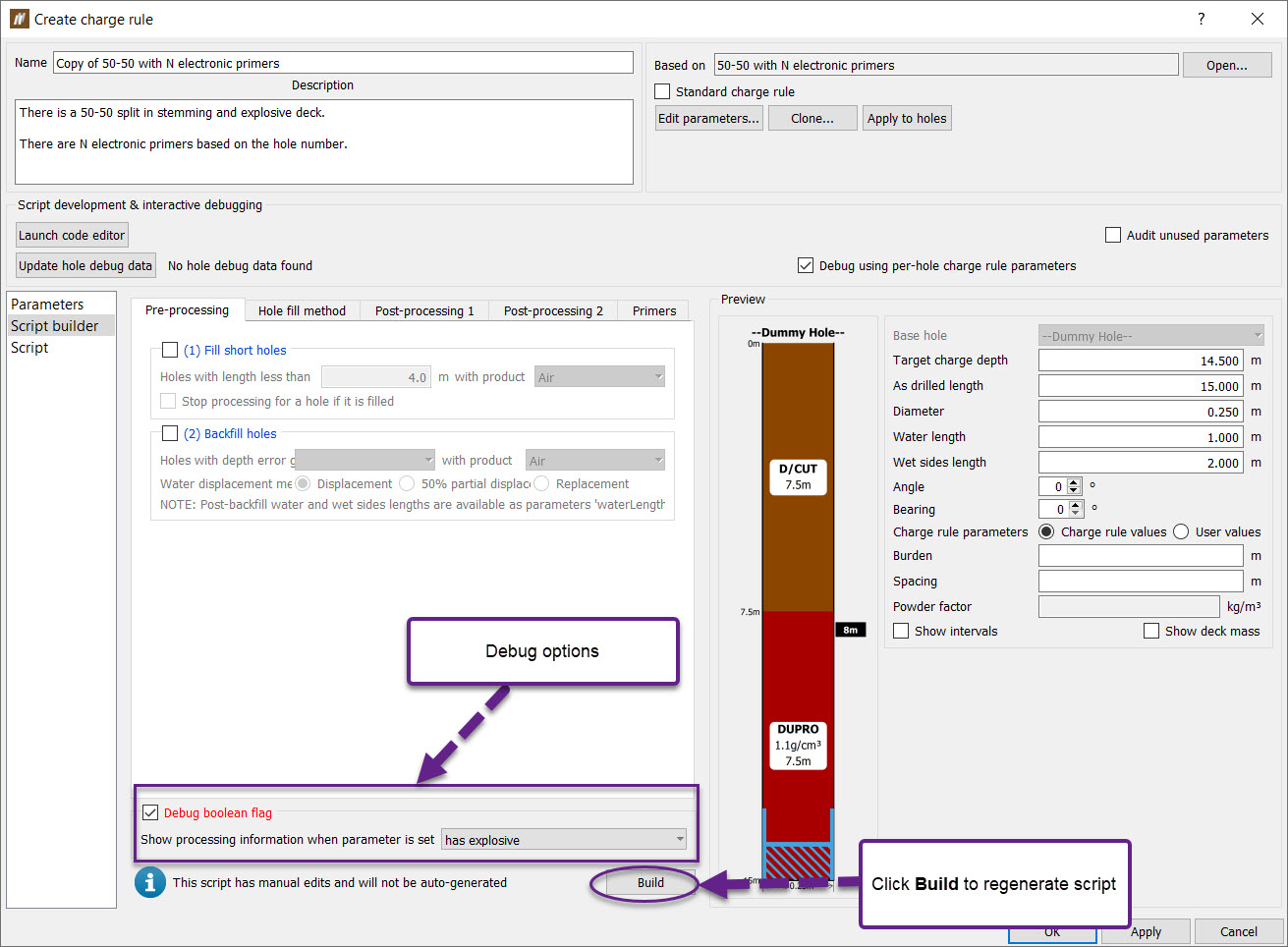
The Script builder tab provides a user-friendly interface for users to define the conditions under which to fill holes. It was created for customers who do not want to use the Scripting tab to create charge rules. The script is generated based on the options selected by clicking the Build button at the bottom of the window on the left-hand side.
Note: Building an auto-generated script will overwrite anything currently contained in the Script.
Directly above the Build button in the bottom right hand corner is the Debug option. This allows you to print debug statements to the report window, through the use of a Boolean charge rule parameter.
There are five sub-tabs which belong to this section: Pre-processing, Hole fill method, Post-processing 1,Post processing 2 and Primers.
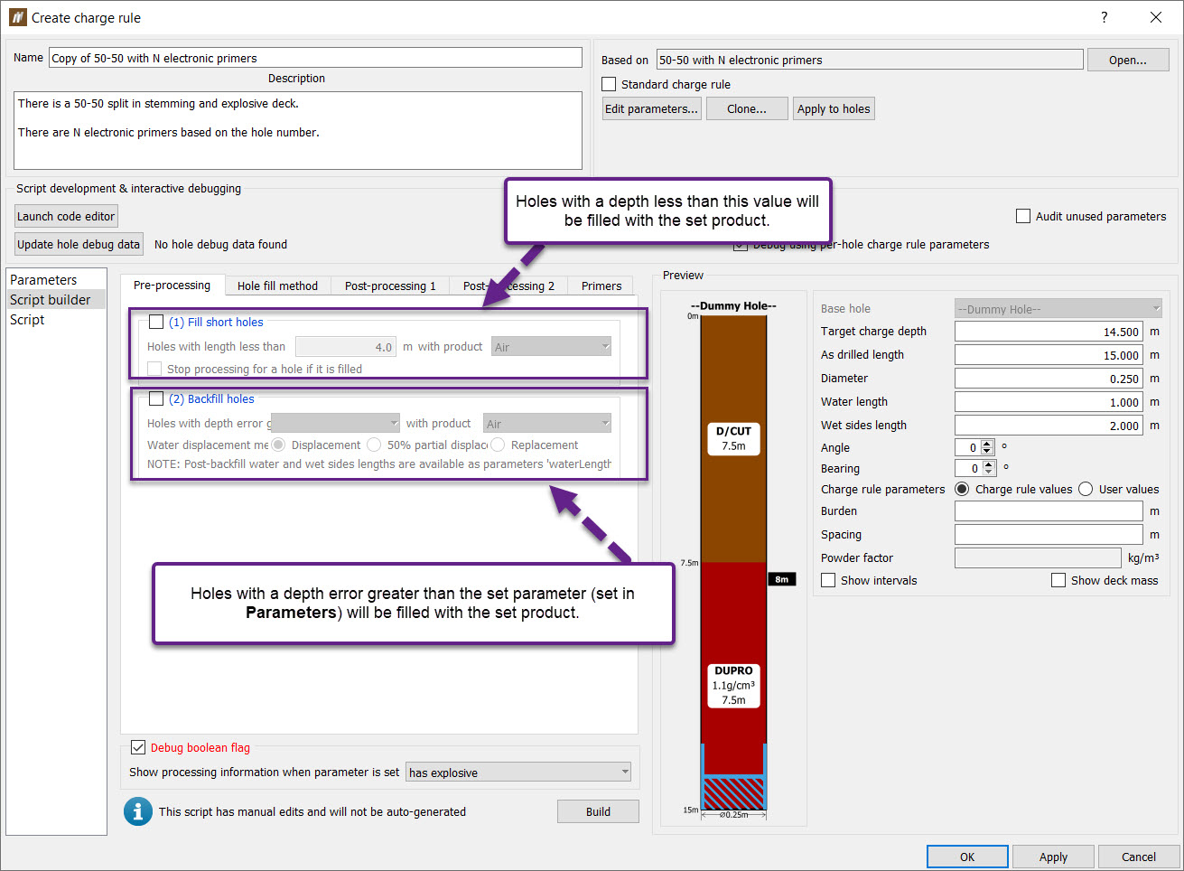
Pre-processing
The Pre-processing sub-tab contains two conditions: the maximum depth at which a hole should be filled with a user-defined product (1. Fill short holes) and the minimum depth error at which to backfill holes with a user-defined product (2. Backfill holes).
The depth error is defined as:

The products available in the drop down list are Air, Drill Cuttings, and any Blast Product charge rule parameter defined on the Parameters tab.
The Water displacement method defines how the water level in the hole should be re-calculated, as a result of any backfill. Depending on the option, this will give you a new water level to use in future calculations.
-
Displacement— Any length of backfill completely displaces any length of water in the hole. i.e a water length of 2m before backfill, will result in a water length of 2m after backfill.
-
50% partial displacement — The length of backfill will displace 50% of the same length of water. i.e a water length of 1m before 1m of backfill, results in a final water length of 0.5m after backfill.
-
Replacement — The length of backfill completely replaces the same length of water. i.e a water length of 1m before 0.5m of backfill, results in a final water length of 0.5m after backfill.
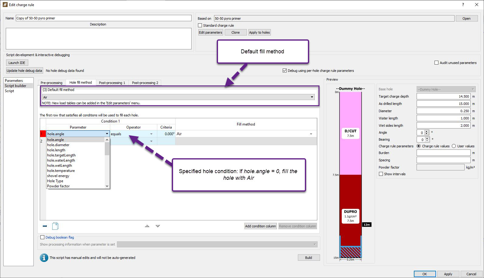
Hole filled method
The Hole filled method sub-tab is used to define a set of conditions: a default condition and other specified conditions.
The default fill method is the only mandatory option for generating scripts. It defines by what method a hole should be filled. The options available in the drop down list are Air, Drill Cuttings or any Load table charge rule parameter.
A specified condition consists of three components: a parameter (which could be a standard parameter such as angle, diameter or length, a hole property set in the Site > Setup > Hole Properties panel or a charge parameter set in the Parameters tab), an operator and a fill method. The fill method is applied, when the said condition is true. In the event where a hole does not satisfy any of the specified conditions, the default condition will be used.
Post-processing 1
The Post-processing 1 sub-tab is used to address intervals added to affected holes as well as water and wet sides. It contains two main options: 4) Fill an interval, 5) Enforce minimum stemming and 6) Replace (non-water resistant) explosive decks affected by water and wet sides.
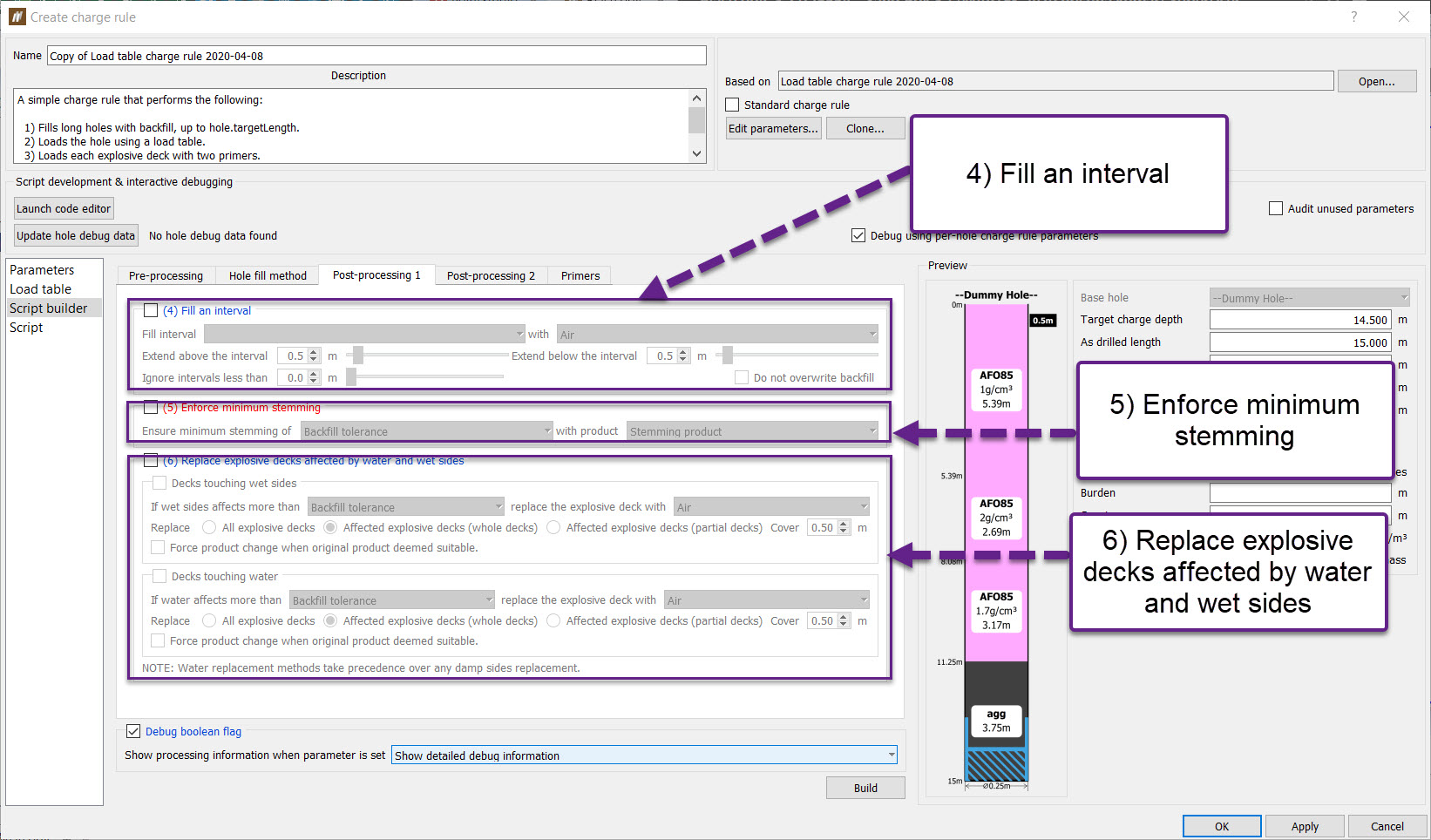
Fill an interval
Enabling this option will fill a given interval with the selected product. In addition, above and below the interval can also be filled to the desired length.
The intervals available to select are any Interval label charge rule parameter defined on the Parameters tab.
The products available in the drop down list are Air, Drill Cuttings, any Blast Product or Load table charge rule parameter defined on the Parameters tab.
The extend above and extend below options fill above and below the interval by the given length, with the product or load table selected.
Optionally, intervals with length less than some tolerance can be ignored by specifying a value greater than 0 for the Ignore intervals less than field.
Note: This will overwrite any products currently in the interval.
Enforce minimum stemming
The Enforce minimum stemming option will replace explosive product at the top of the hole with stemming product, should the amount of explosive product be below the set minimum stemming length.
Replace (non-water resistant) explosive decks affected by water and wet sides
Enabling this option will replace water and/or wet sides affected decks that do not have water/damp resistant products.
It is recommended that the replacement product is water/damp resistant, however this is not mandatory.
The products available in the two drop down lists are Air, Drill Cuttings, and any Blast Product charge rule parameter defined on the Parameters tab.
This option can replace any or all decks should they be touching water or wet sides. If both options are enabled, decks in water are always tested and replaced first.
Only decks that do not already contain water/damp resistant products will be replaced, if the given water tolerance is exceeded.
The following methods exist to replace decks:
- All explosive decks — If any explosive deck is affected by more water/wet sides than the given tolerance, all explosive decks in the hole are replaced.
- Affected explosive decks (whole decks) — If any individual explosive deck is affected by more water/wet sides than the given tolerance, that specific explosive deck is replaced.
- Affected explosive decks (partial decks) — If any individual explosive deck is affected by more water/wet sides than the given tolerance, only the portion affected by water/wet sides is replaced.
Additionally, the user can supply a cover length, which will extend the fill above the water/wet sides level.
Post-processing 2
The Post-processing 2 sub-tab is used to combine and replace explosive/inert decks based on height. It is also used to load primers according to specific conditions defined.
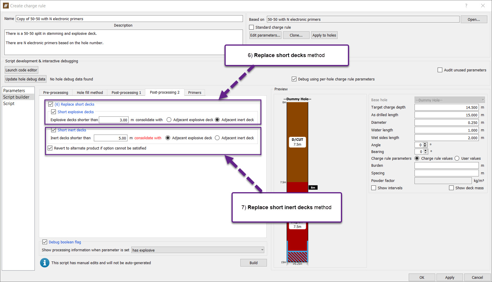
Replace short decks
Enabling this option will remove decks shorter than the supplied tolerance, and attempt to combine with nearby decks.
Short decks that are identified are then consolidated with nearby decks, by the following method:
-
Adjacent explosive deck - the product of the bottom adjacent deck is checked first. If it is explosive, this product is used. If the product is not explosive, the product of the top adjacent deck is checked. Again, if it is explosive, this product is used. If the product is not explosive, the function will error out explaining it cannot replace the product using the desired option. This can be avoided by enabling the Revert option, that will fallback to using an inert deck instead (see next option).
-
Adjacent inert deck - the product of the top adjacent deck is checked first. If it is inert, this product is used. If the product is not inert, the product of the bottom adjacent deck is checked. Again, if it is inert, this product is used. If the product is not inert, the function will error out explaining it cannot replace the product using the desired option. This can be avoided by enabling the Revert option, that will fallback to using an explosive deck instead (see option above).
Replace short inert decks
Enabling this option will remove inert decks shorter than the supplied tolerance, and attempt to combine with nearby decks.
-
Adjacent explosive deck - If the inert deck is shorter than the defined length, it will be combined with the adjacent explosive deck, should this option be chosen.
-
Adjacent inert deck - If the inert deck is shorter than the defined length, it will be combined with the adjacent inert deck, should this option be chosen.
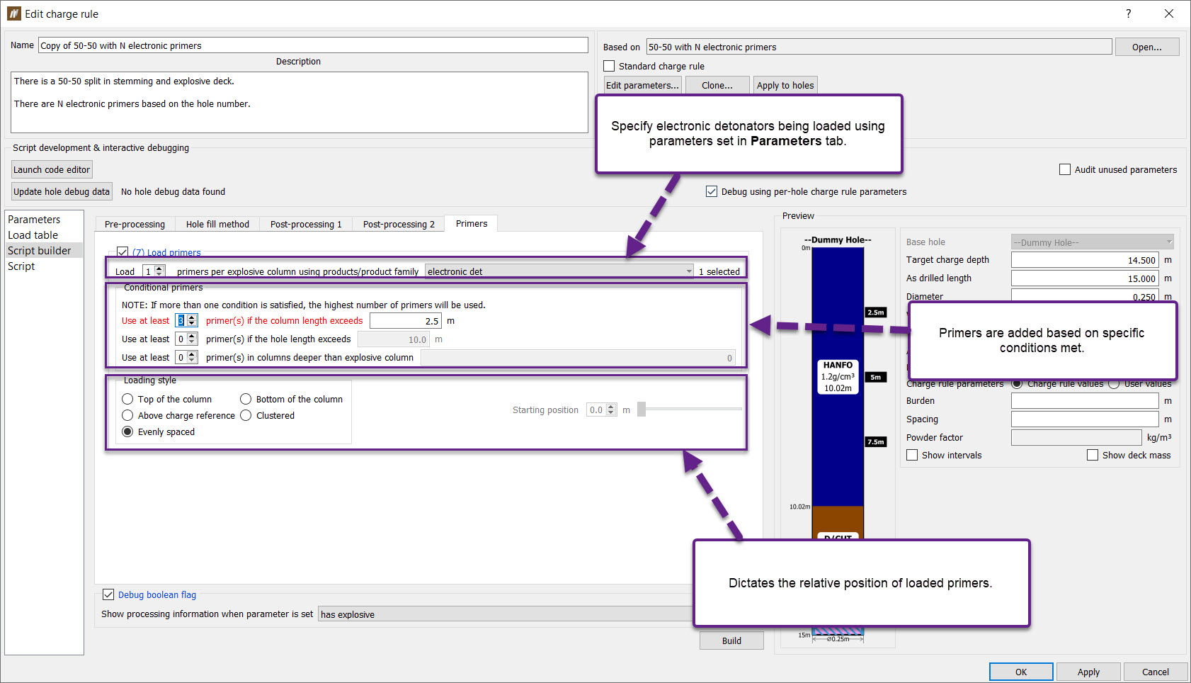
Primer
The Primers tab adds primers to selected holes in a pattern specified in one of the options.
-
Load x primers per explosive column using products/ product family — Adds x primers to a column containing the selected products/ product families.
-
Conditional primers — Adds primers if certain conditions are satisfied. If more than one condition is satisfied, the highest number of primers are used.
-
Column length — If the column length exceeds y metres, at least x primers will be loaded in that explosive column.
-
Hole length — If the hole length exceeds y metres, at least x primers will be loaded in each explosive column.
-
Columns deeper than explosive column y — If the column length exceeds the length of the specified explosive column (to select the first column for example, y = 0), at least x primers will be loaded in that column.
-
-
Loading style — This option dictates the relative position of loaded primers.
Script
The Script tab is designed to create complex charge rules using an external editor. These editors provide tools that supports JavaScript, such as hints, and syntax highlighting.
Charge rule parameters and custom hole properties can be referenced while scripting using the Charge Rule API. Charge rule parameters are defined in the Edit charge parameters tab and set in the Parameters tab. Custom hole properties are defined in the Setup > Site > Hole properties tab (see Custom hole properties).
Editing charge rule scripts using an external editor
Two editors are currently supported for editing charge rule scripts:
-
Notepad++ (64-bit version) — Notepad++ is a small and simple text editor, regularly used for its ability to recognise hundreds of file formats. It's usage as a code editor is not widespread but still provides the minimum functionality required to support JavaScript editing.
-
Microsoft Visual Studio Code — A small and light weight code editor, released as a stripped down free version of Microsoft's flagship code editor - Visual Studio. This editor is best supported by installing the extension ESLint. This can be added inside Visual Studio Code, once it has installed.
Auto-complete
Both supported editors provide a functionality known as Auto-complete. This serves to provide helpful hints for functions and parameters to use within the associated script.
For example, typing in hole.fill provides the following information, explaining the usage of the fill function:
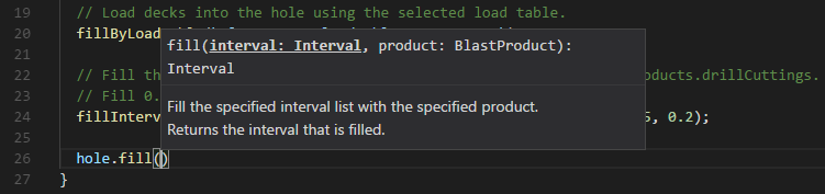
This shows us that the fill function takes in two parameters:
- An interval (of type Interval)
- A product (of type BlastProduct)
In addition, we can also see that the function will return an interval (of type Interval).
Microsoft Visual Studio Code is the preferred code editor, as it provides the most functionality. There is no additional work required in order for auto-complete to work as explained above. User provided charge rule parameters will also be available through the use of the params object, i.e params.dryChargeProduct.
In Notepad++ (64-bit version), auto-complete will only provide help for hole related functions and properties. In order to enable this functionality, the javascript.xml provided in Program Files/Maptek/BlastLogic 2020/etc/snippets must be copied to Program Files/Notepad++/plugins/APIs.
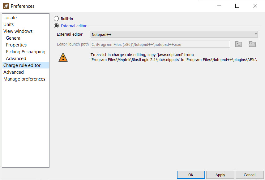
Selecting a preferred editor
Selecting a preferred editor can be performed in the Preferences tab:
If none of the supported editors are installed, only the built-in will be selectable.
Please note that selecting an external editor will disable the built-in editor - it will still be available to view, however it will be read only.
Launching an editor and editing guidelines
Editing a charge rule script using an external editor can be done by clicking the Launch editor button, available at the top of the Script tab when editing a charge rule.
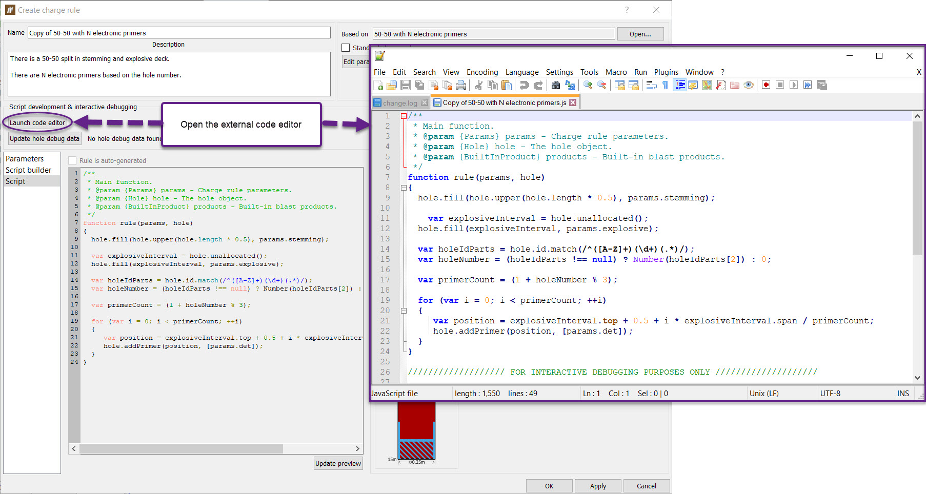
This button will be disabled if there is no external editor selected in user preferences, the rule is auto-generated, or the rule has been published.
Please note that closing the charge rule will also sever the connection between the charge rule and the external editor. This may result in the script closing in the external editor.
Editing within the external editor will automatically be recognised by the charge rule every time the user saves (Ctrl-S). It is recommended to save often.
Editing guidelines
In order to allow the auto-complete functions to provide the best hints for your script, JavaScript functions must be commented using strict JSDoc format.
This format outlines the function parameter types, and enables auto-complete to provide hints for that specific parameter type.
Functions should be commented similar to that seen in the image above for the Rule function. Without this information, auto-complete will not show hints during editing.
At a minimum, functional documentation should contain:
- A comment about what the function will do.
- a list of @param {<object>} <parameter_name> entries describing the parameter types and what they represent.
- (optionally) an @returns {<object>} entry describing what type the function will return.
The supported object types are as follows:
-
Params — A parameters object, containing the user specified charge rule parameters, e.g params.dryChargeProduct.
-
Hole — A hole object, containing functions and properties relating to the specific hole.
-
BuiltInProduct — Holds a pre-defined list of built in blast products. These products are of type BlastProduct.
-
LoadTable — A load table, defining specific rules about how a hole is to be loaded.
-
FilteredBlastProductFamily — A filtered family of blast products, usually corresponding to down hole delays and surface delays.
-
BlastProductFamily — A family of blast products, usually corresponding to electronic detonators and detonating cord delays.
-
Deck — Contains deck properties, corresponding to a deck in the hole.
-
DeckList — A list of decks, corresponding to those loaded into specific sections of the hole.
-
Interval — An object that contains information corresponding to a top and bottom depth. This object may also have sub intervals.
-
IntervalLabel — A label given to at least one interval, usually corresponding to an interval intersecting with a hole.
-
BlastProduct — A product for use to charge a hole.
-
-
Click OK or Apply in the Edit Charge Rule panel to save the charge rule edits.
Publishing a charge rule
Publishing a charge rule to the server allows other server users to access and load the charge rule. After publishing a charge rule, the Rules and Parameters of the charge rule can no longer be modified, however the Name and Description are still editable.
You must publish a charge rule to apply it to published holes. You can see the charge plan preview without publishing the charge rule first. However, you will be prompted to publish the charge rule when saving the previewed charge plans for the holes.
To publish a charge rule to the server, follow these steps:
-
In the data explorer, in the charge rules container, right-click on the charge rule and select Publish... from the context menu. Alternatively, select the charge rule in the data explorer and on the Charge Rule context ribbon, in the Publish group, select Publish.
The Publish Charge Rule panel will appear. This panel contains any errors, which you can fix by selecting the Open option to fix the error in the Action column. If not errors are present, BlastLogic will present a publishing message in the table.
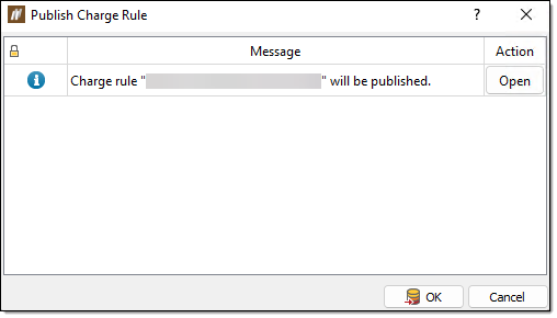
-
Click OK. BlastLogic will publish the charge to the server.
Applying a charge rule
After creating and publishing a charge rule, you can apply it to a group of holes.
To apply a charge rule to a group of holes, follow these steps:
-
In the data explorer, in the charge rules container, double click on the desired charge rule. The Edit Charge Rule Defaults panel will appear.
-
Select a set of holes in the view window or data explorer.
-
Select Apply to holes.... Alternatively, you can right-click on the charge rule in the data explorer and select Apply to Holes... from the context menu.
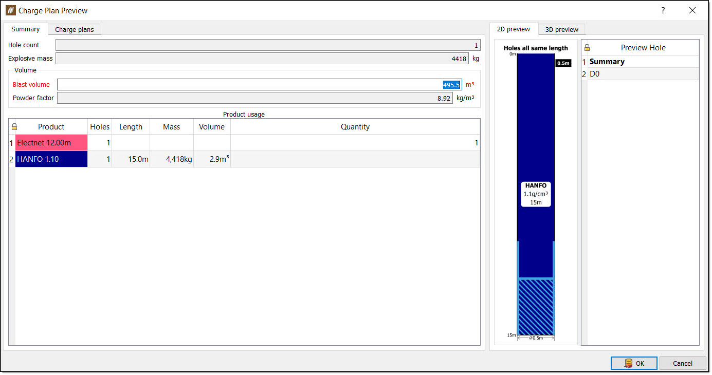
The Charge Plan Preview panel will appear.
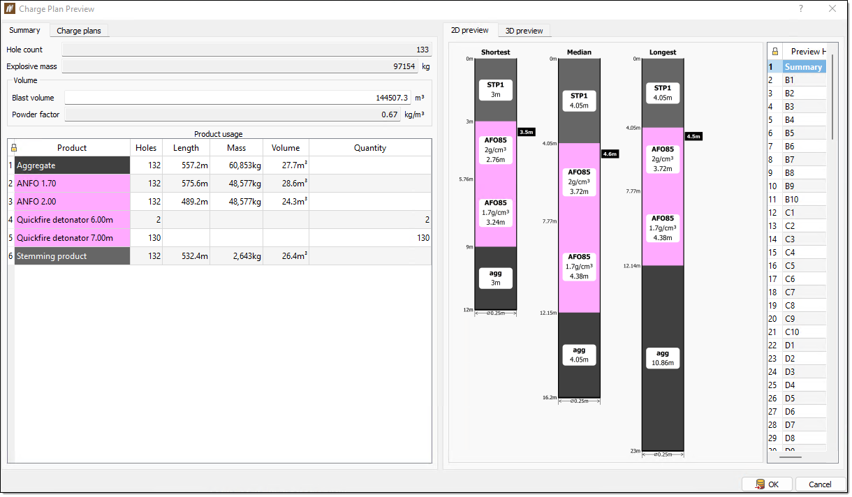
In this panel, you can also click on the Charge plans tab and 3D preview tab to view more charge plan information.
-
Review the charge rule application preview. Ensure the information in the Summary and Charge plans tabs is as desired. You can also view the hole charge plans using the 2D preview and 3D preview tabs.
-
Click OK to apply the charge plan to the holes.
Design Charge Depth
The Design Charge Depths tool allows you to update the design charge depth and charge standoff after the blast has been imported into BlastLogic. The charge depth and charge standoff are updated by setting the required value in relation to a specified reference surface.
Setting the charge standoff will update the charge depth to a depth at which the reference surface would intersect with the hole charge depth minus the value of the charge standoff.
Setting the charge depth will update the charge standoff to a depth at which the reference surface would intersect the hole charge depth minus the calculated value of the charge standoff.
To update the design charge depth and charge standoff:
-
Select the holes you wish to edit in the data explorer or view window.
-
On the Charging ribbon, in the Design group, select
 Design Charge Depths. The Edit Design Charge Depths panel will appear.
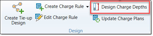
-
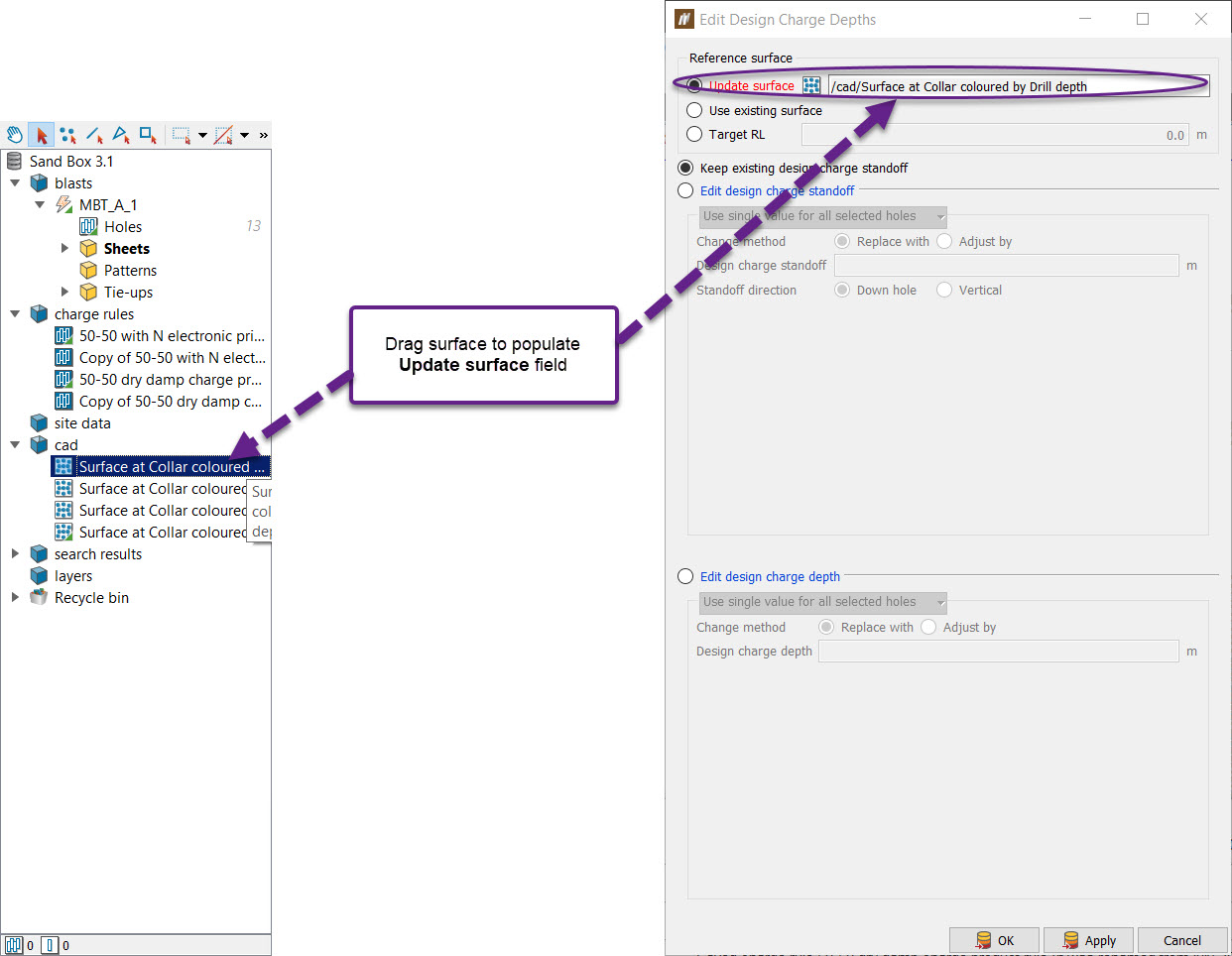
Specify the reference surface by selecting one of the following:
-
Update surface — This field enables a surface to be used to update the charge depth using the existing charge standoff or a newly defined charge standoff.
-
Use existing surface — Use the surface already attached to the holes. If one has not been attached, the current charge depth and standoff will be used as reference.
-
Target RL — The desired RL to based charge depth and charge standoff calculations from.
-
Update using a new surface
-
Select Update surface.
-
Drag and drop the desired surface from the Windows Explorer to the Update surface field.
-
If the holes already have a valid charge standoff, select Keep existing design charge standoff. Otherwise, select either Edit design charge standoff to specify a new charge standoff, or Edit design charge depth to specify a new charge depth. Note: If the holes already have a valid charge standoff or charge depth, the user will have to confirm that they meant to change the desired value before they are allowed to continue.
-
Enter the charge standoff/charge depth value(s). If editing charge standoff, enter the standoff direction.
-
Click OK. Confirm any warning messages to save the value(s) to the holes. Note: When using a new surface, the surface chosen will be saved as an attachment to the blast the holes belong to. If a previous reference surface was attached to these holes, it will be replaced with the new surface. If the holes are published and the surface is not published, the surface will be published to the server when the user clicks OK.
Update using a Target RL
-
Select Target RL.
-
Enter the desired Z value.
-
Continue from step 3 above — Update using a new surface.
Automatically update using an existing surface
-
Select Use existing surface. This will check the attachments for the selected holes to see if a reference surface has previously been attached to the holes using the steps above. If there is no existing reference surface, the tool will calculate an implicit horizontal surface for each hole using the depth of the previous charge standoff value.
-
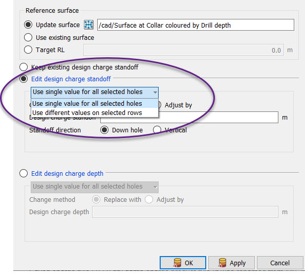
Select Edit design charge standoff.
Editing design charge standoff
- Select the update method for the charge standoff. If each hole can have the same charge standoff value, select Use single value for all selected holes. Otherwise, select Use different values on selected rows. Using this method, different values can be defined for each row. Use the Row field to type the letter identifying the row (e.g. A for all A1, A2, ..., etc holes). This field is not case sensitive.
-
Select the Change method. Replace with will replace the current charge standoff with a new value. Adjust by will adjust the current charge standoff value to be greater by the amount of the new value.
-
Select the Standoff direction.
-
If using a different value for each row, select whether unspecified rows should use a default by checking Default for other rows.
- Click OK or Apply.
Editing design charge depth
-
Select the update method for the charge depth. If each hole can have the same charge depth value, select Use single value for all selected holes. Otherwise, select Use different values on selected rows.
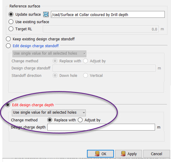
Using this method, different values can be defined for each row.
Use the Row name field to type the letter identifying the row (e.g. A for all A1, A2, ..., etc holes). This field is not case sensitive.
-
Select the Change method- either Replace with or Adjust by. The Replace with option will replace the current charge standoff with a new value. Adjust by will adjust the current charge depth value to be greater by the amount of the new value.
-
If using a different value for each row, select whether unspecified rows should use a default by checking Default for other rows.
-
Click OK or Apply.
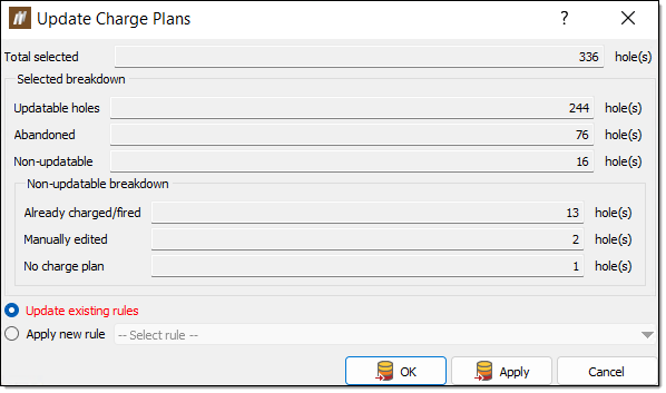
Update Charge Plans
The Update Charge Plans tool allows you to update a charge plan. If you make changes to the hole geometry and you have already applied a charge plan, you must update the charge plan manually.
To update a charge plan, follow these steps:
-
Select the holes you have made changes to.
-
On the Charging ribbon, in the Design group, select Update Charge Plans.
The Update Charge Plans panel will appear. BlastLogic displays the information about the holes, including a breakdown of non-updatable holes.
-
Select a radio button option at the bottom of the panel. You can select one of the following options:
-
Update existing rules — Select this option to reapply the existing charge rules linked to the selected holes.
-
Apply new rule — Select this option to apply a new charge rule to the selected holes. Select the desired charge rule using the -- Select rule -- drop-down.
-
- Click OK or Apply. The Charge Plan Preview panel will appear.
-
Click OK. If the changes applied are undesirable, click Cancel.
Create Tie-up Design
The Create Tie-up Design tool allows you to create a tie-up design for the selected blast. BlastLogic provides you with the option to create either of the following tie-up blast designs:
-
Pyrotechnic
In a pyrotechnic tie-up, operators physically connect detonators and set the initiation timings manually. -
Electronic
In an electronic tie-up, you can program the initiation timings.
BlastLogic will automatically detect if you create a pyrotechnic or electronic blast by the type of detonators you add to the tie-up design. If you use a mix of detonator types, BlastLogic will create a hybrid design.
Before creating a tie-up design for a group of holes, the holes must have an associated charge rule. For steps on applying a charge rule to a group of holes, see Applying a charge rule.
Selecting the Create Tie-up Design tool
To select the tool, follow these steps:
-
Select the desired blast in the view window or data explorer.
-
On the Charging ribbon, in the Design group, select Create Tie-up Design. Alternatively, you can right click on a blast Tie-ups container in the data explorer and select New Tie-up Design from the context menu.
The Tie-up Editor will appear.
Creating an electronic tie-up
In an electronic tie-up, you can program the initiation timings and edit the detonator timings. To generate an electronic tie-up, there are three components which you need to define:
-
Timing horizons
A timing horizon is associated with hole intervals which define parts of the hole that need to have a specific timing for the tie-up. -
Hole timings for each horizon (usually through creating timing roses or lines)
Timing roses and timing lines provide you with a central control for adding timing to holes. You can associate holes with a timing rose or a timing line. Adjusting the timing rose/line will then automatically adjust the timings of each hole associated with it. -
Harness wire
In order to detonate explosives, electronic tie-ups need initiation systems. Initiation systems are added to the tie-up using the Wire tab. Harness wire is used to physically tie-up the electronic detonators so the initiation timings assigned to them can be programmed by a logger.
To create an electronic tie-up, follow these steps:
-
Select the desired blast in the view window or data explorer.
-
On the Charging ribbon, in the Design group, select Create Tie-up Design. Alternatively, you can right-click on a blast Tie-ups container in the data explorer and select New Tie-up Design from the context menu.
The Tie-up Editor will appear.
-
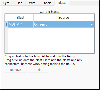
Select the Blasts tab.
-
Select the desired blast data source. To do this, follow these steps:
-
In the Current blasts table, select the Source column drop-down. BlastLogic will display the data sources available for the corresponding blast.
-
Select the desired source from the Source drop-down. The drop-down contains four types of sources:
-
Plan
Select the Plan option to create a tie-up using only charge plan data. In this case, no loaded or reconciled data is included in the tie-up. This option is in bold to signify that it is a special data type that you can only access in the tie-up editor and fly rock modelling tool. -
Current
Select the Current option to create a tie-up using reconciled data. If there is no reconciled data, BlastLogic will load the plan data instead (but not any loaded data). This option is in bold to signify that it is a special data type and not a snapshot. -
Reference design snapshot
The name of the reference design snapshot will appear as an option in the drop-down. For example, in the image below, the snapshot HP, is in bold to represent that it is the reference design snapshot. Select this option to create a tie-up using the reference design snapshot data.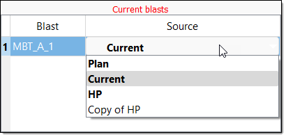
-
Other snapshots
Any other snapshots related to the blast will also appear in the drop-down. Select the name of the desired snapshot to create a tie-up using that snapshot’s data. These snapshots will not be in bold.
-
-
-
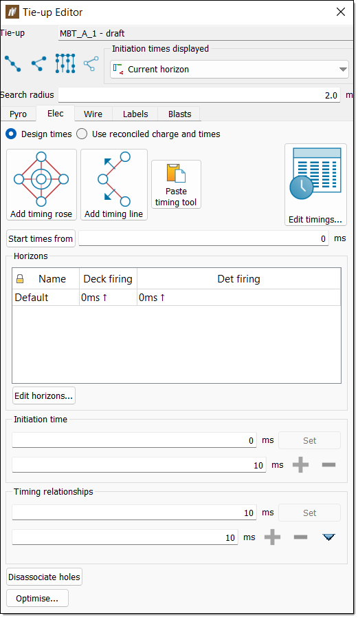
Select the Elec tab in the panel.
-
Optionally, edit the timing horizons. A timing horizon specifies how you wish to assign timings to an interval of a hole. To edit these, select Edit horizons.... The Edit Horizons for <tie-up name> panel will appear.
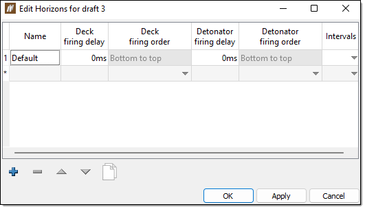
The Default horizon covers the entire length of the hole. No intervals are assigned to this horizon and therefore any parts of the hole that are not associated with an interval will appear in this default horizon. You can add horizons by clicking
 and entering the appropriate information into the table.Expand for more information on the edit horizons options
The table contains the following columns:
-
The Deck firing delay is the delay between multiple decks within a horizon.
-
The Detonator firing delay is the delay between multiple detonators within a deck.
-
The Detonator firing order is the order between multiple detonators within a deck.
The panel contains the following options:
-
To remove a timing horizon, select the horizon and click
. -
To clone a timing horizon, select the horizon and click
. -
To reorder the timing horizons, select the horizon you wish to move and click the
and arrows.
-
-
Add a timing tool. In BlastLogic there are two timing tools you can use to automatically assign initiation timings to holes:
-
Timing line
To create a timing line, follow these steps-
Select the desired horizon from the Horizons table in the Tie-up Editor.
-
Select the Add timing line tool from the Tie-up Editor.

The status bar will appear at the bottom of the view window.

-
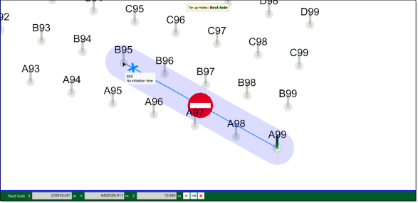
Click the desired points in the view window to form the timing line. BlastLogic will connect the clicked points to display the timing line.
Expand for an alternative selection method.
Alternatively, you can enter the initial desired point into the First point coordinate fields on the status bar and select
 to confirm the point. The First point label will change to Next point which allows you to enter the next line point. You can continue this process until you have entered all the desired timing line points.
-
Press Enter or click
 to complete the timing line. A common timing line is V-shaped and points towards the holes, with a different burden relief on each side.
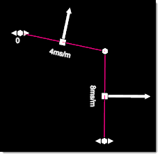
-
Adjust the timing line. You can use the following options to adjust the timing line:
-
To select a point on a timing line, ensure the
 Select points mode is selected in the data explorer toolbar.
 -
To adjust the burden relief of a timing line segment, drag the arrow for that segment using the middle mouse button.
-
To adjust the shape of the timing line, drag a point on the timing line using the middle mouse button.
-
To move the timing line, select all of the points on the timing line and drag one of the points using the middle mouse button. You can select all of the segments of the timing line by right-clicking on the timing line and selecting Select All Segments from the context menu.
-
To adjust the initiation time of the timing line, drag the arrows either to the left (to decrease) or right (to increase) using the middle mouse button.
-
To split a single timing line segment into two segments, right-click on the segment and select Split Segment from the context menu.
-
To delete a single timing line segment, right-click on the segment and select Delete Segment from the context menu.
-
To copy the timing line to another location, right-click on the timing line and select Copy Timing Line from the context menu.
-
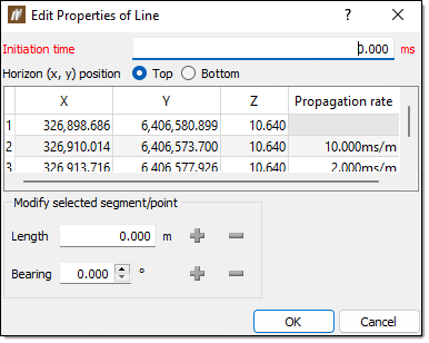
To view and edit the properties of a timing line, right-click on the line and select Edit Properties of Line... from the context menu. The Edit Properties of Line panel will appear.
-
To delete the timing line, right click anywhere on the timing line and select Delete Timing Line from the context menu.
-
When drawing a timing line, BlastLogic will associate all holes without initiation times with the timing line. To associate only a selected number of holes to the timing line, select a set of holes, right-click on the timing line and select Associate with Selected Holes from the context menu. This tool can be useful when you add multiple timing lines and timing roses to a tie-up.
Expand for more information on line initiation timings
A timing line has a variable number of edges each with a different burden relief value. The software determines which edge of the timing line the hole should be under the influence of and then uses the distance from edge to the hole to calculate its initiation time.
The distance calculations only consider the X and Y of the hole collars and of the timing line. Additionally, a fixed delay can also be added to the initiation times for holes associated with a timing line
-
-
-
Timing rose
To create a timing rose, follow these steps:-
Select the desired horizon from the Horizons table in the Tie-up Editor.
-
Select the Add timing rose tool from the Tie-up Editor.

The status bar will appear at the bottom of the view window.

-
Click the point you wish to place the timing rose in the view window. BlastLogic will create an example timing rose centred at this point.
Expand for an alternative selection method.
Alternatively, you can enter the initial desired point into the First point coordinate fields on the status bar and select
to confirm the point. The First point label will change to Second point which allows you to enter the point you wish the timing rose to extend to. -
Click another point which sets the size of the timing rose. The further away you click from the first point, the larger the timing rose will be.
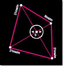
The timing rose is diamond shape with equal burden relief values for each of its four directions. The larger the timing rose, the larger the burden relief in ms/m is for each corner of the timing rose. You can alter the orientation of the rose to adjust the direction of the burden relief. vice versa?
-
Adjust the timing rose. You can use the following options to adjust the timing rose:
-
To select a point on a timing rose, select the
Select points in the data explorer toolbar. -
To adjust the shape of the timing rose, drag a point on the timing rose using the middle mouse button.
-
To move the timing rose, drag the point in the middle of the rose using the middle mouse button.
-
To copy the timing rose, right-click on the timing rose and select Copy Timing Rose from the context menu.
-
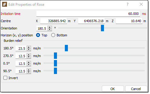
To view and edit the properties of a timing rose, right-click on the line and select Edit Properties of Rose... from the context menu. The Edit Properties of Rose panel will appear.
-
To adjust the initiation time of the timing rose, drag the centre arrows either to the left (to decrease) or right (to increase) using the middle mouse button.
-
To invert the timing rose, right-click on the timing rose and select Invert from the context menu.
-
To delete the timing rose, right click anywhere on the timing rose and select Delete Timing Rose from the context menu.
-
When drawing a timing rose, BlastLogic will associate all holes without initiation times with the timing rose. To associate only a selected number of holes to the timing rose, select a set of holes, right-click on the timing rose and select Associate with Selected Holes from the context menu. This tool can be useful when you add multiple timing lines and timing roses to a tie-up.
Expand for more information on rose initiation timings
A timing rose has four sides each with a different burden relief value. The initiations times for holes assigned to a timing rose are calculated based on the position of the hole from the timing rose and which side of the timing rose is closest to the hole. The distance between the hole and the timing rose and the corresponding burden relief for the closet side is then used to calculate the initiation time.
The distance calculations only consider the X and Y of the hole collars and of the timing rose. Additionally, a fixed delay can also be added to the initiation times for holes associated with a timing rose.
-
-
-
-
Add harness wire. To do this, follow these steps:
-
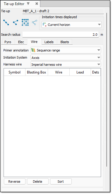
Select the Wire tab in the tie-up editor.
-
Select the desired attributes from the Primer annotation, Initiation System and Harness wire drop-downs.
Note:You can find a list of the available initiation system and harness wire products in the blast product catalogue. You can find this catalogue by selecting Blast Product Catalogue, from the Setup group, on the Home ribbon. For more information on this catalogue, refer to the Blast product catalogue section of the setup page.
 Expand for information on the DetNet - DigiShot initiation system
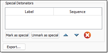
When using the DetNet - DigiShot initiation system, you can mark holes as special to indicate that they are considered out of sequence. You can use this special tag to mark either an ad hoc and/or a re-drill hole. The special hole contains detonators that were not a part of the plan.
To mark holes as special, select the holes and click Mark as special.
To remove special status from selected holes, select the holes and click Mark as unspecial.
-
Select the desired connection mode.
Expand for more information on the connection modes.
There are four connection modes to select from:
-
Row-by-row

The row-by-row mode ties up all holes inside the selected cursor range.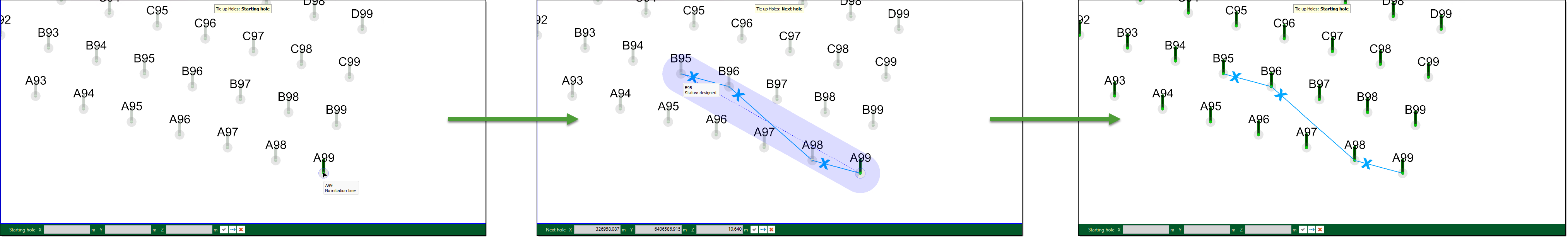
-
Hole-by-hole

The hole-by-hole mode ties up a series of holes one-by-one.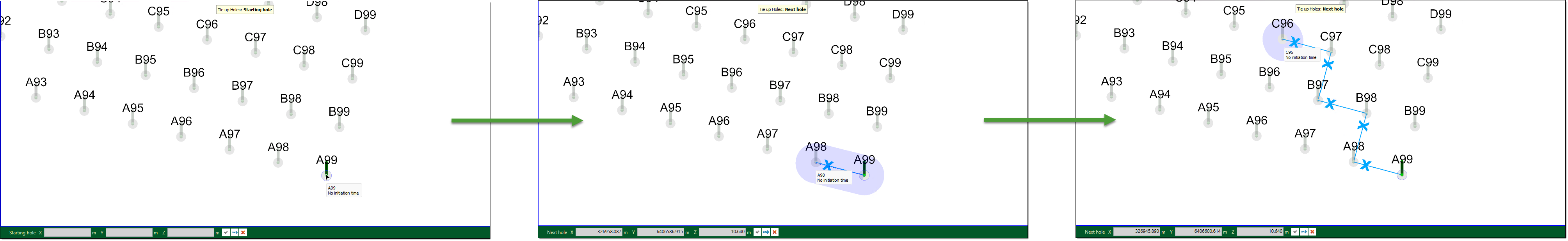
If you attempt to connect two holes over a distance greater than the connector length, BlastLogic will prevent you from connecting the holes.
-
Auto-fill

The auto-fill mode automatically ties up rows or echelons across a control line template.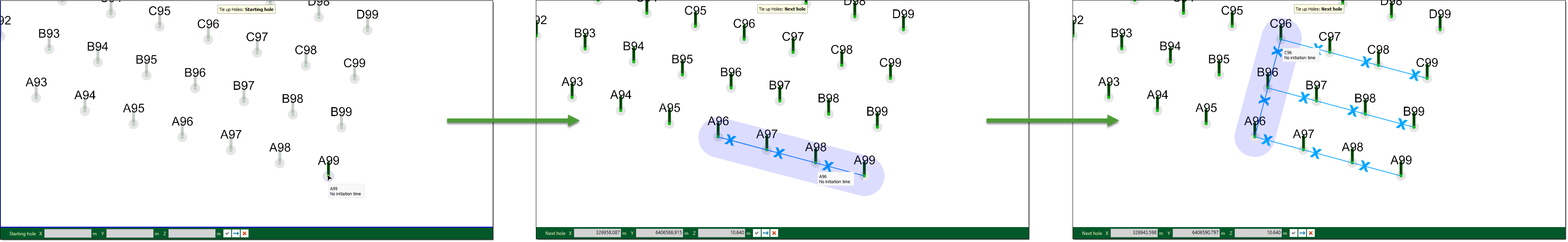
-
Dummy hole-by-hole

The dummy hole-by-hole mode ties up a series of hole one-by-one and creates dummy holes when you click in free space. Creating dummy holes allows you more flexibility when creating the shape of the tie-up.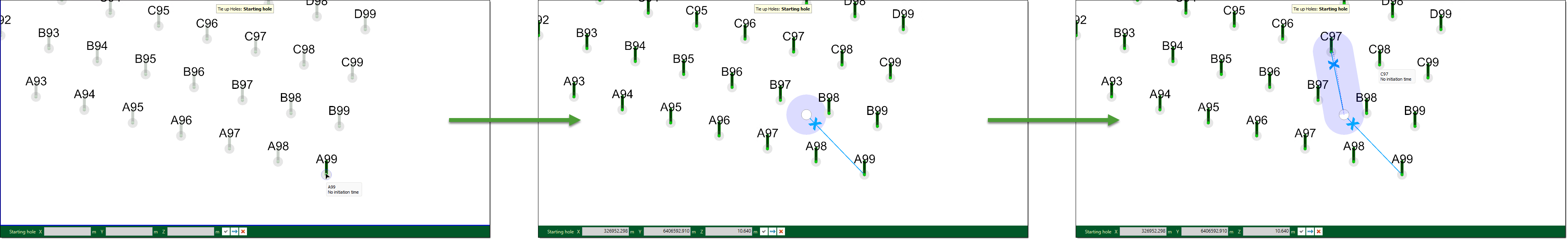
Note:You can only connect harness wire using holes along a line
or hole by hole . You cannot connect harness wire by automatically filling in echelons across a control line .
-
-
Connect the desired holes in the view window by selecting the holes in a sequential order. The connections will appear in the tab table.
 Expand for more information on connecting the wire
As you connect the wire between the holes in the view window, BlastLogic displays a line between the consecutively clicked holes. These lines have unique symbols and colours to represent each type of harness wire. You can view details of each connection in the editor table.
The limits for the maximum wire length, maximum lead length, and maximum detonator count per harness wire run are set as properties of the electronic initiation system in the blast product catalogue. If a limit is exceeded, the cell in the harness wire table will be highlighted red. Hover over the cell to see the tool tip error message.
-
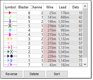
Optionally, you can use the following options to adjust the connections:
-
To reverse the direction of a harness wire run, select the harness wire run in the table and click Reverse.
-
To delete a harness wire run, select the harness wire run in the table and click Delete.
-
To sort the harness wire runs in the table, click Sort.
-
Creating a pyrotechnic tie-up
A pyrotechnic tie-up uses surface connectors to physically connect detonators between holes in a blast.
To create a pyrotechnic tie-up, follow these steps:
-
Select the desired blast in the view window or data explorer.
-
On the Charging ribbon, in the Design group, select Create Tie-up Design. Alternatively, you can right click on a blast Tie-ups container in the data explorer and select New Tie-up Design from the context menu.
The Tie-up Editor will appear.
-
Select the Blasts tab.
-
Select the desired blast data source. To do this, follow these steps:
-
In the Current blasts table, select the Source column drop-down. BlastLogic will display the data sources available for the corresponding blast.
-
Select the desired source from the Source drop-down. The drop-down contains four types of sources:
-
Plan
Select the Plan option to create a tie-up using only charge plan data. In this case, no loaded or reconciled data is included in the tie-up. This option is in bold to signify that it is a special data type that you can only access in the tie-up editor and fly rock modelling tool. -
Current
Select the Current option to create a tie-up using reconciled data. If there is no reconciled data, BlastLogic will load the plan data instead (but not any loaded data). This option is in bold to signify that it is a special data type and not a snapshot -
Reference design snapshot
The name of the reference design snapshot will appear as an option in the drop-down. For example, in the image below, the snapshot HP, is in bold to represent that it is the reference design snapshot. Select this option to create a tie-up using the reference design snapshot data.
-
Other snapshots
Any other snapshots related to the blast will also appear in the drop-down. Select the name of the desired snapshot to create a tie-up using that snapshot’s data. These snapshots will not be in bold.
-
-
-
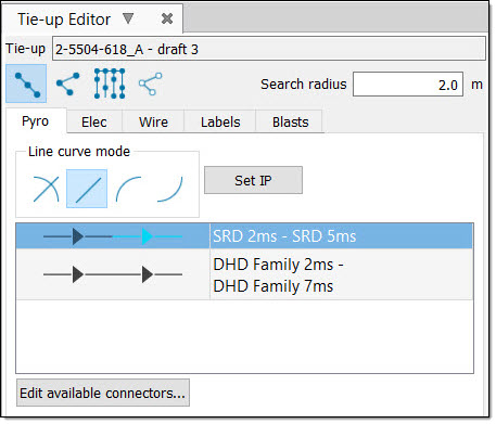
Select the Pyro tab in the panel.
-
Select the connectors you wish to use from the connector table.
Tip!You can add or edit existing connectors using the Blast Product Catalogue tool, located in the Setup group on the Home ribbon. For more information on this catalogue, refer to the Blast product catalogue section of the setup page.
You can also edit or change the connectors by following the steps in the Pyro section of the design page.
-
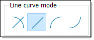
Optionally, set the Line curve mode. BlastLogic allows you to make this selection solely to make each connector easier to see in the view window (for example, to prevent overlapping connectors).
-
Select the desired active connector from the table.
-
Select a tie-up connection mode button in the tie-up editor.
The tie-up holes status bar will appear.
 Expand for more information on the connection modes.
There are four connection modes to select from:
-
Row-by-row
The row-by-row mode ties up all holes inside the selected cursor range.
-
Hole-by-hole
The hole-by-hole mode ties up a series of holes one-by-one.
If you attempt to connect two holes over a distance greater than the connector length, BlastLogic will prevent you from connecting the holes.
-
Auto-fill
The auto-fill mode automatically ties up rows or echelons across a control line template.
-
Dummy hole-by-hole
The dummy hole-by-hole mode ties up a series of hole one-by-one and creates dummy holes when you click in free space. Creating dummy holes allows you more flexibility when creating the shape of the tie-up.
-
-
Select each hole you wish to connect, according to the selected connection mode.
-
Press Enter or double click the last hole to end a sequence of connectors. This allows you to restart a new sequence that is not connected to the previous sequence without closing and re-opening the status bar.
Tip!You can change the connector type and connection mode at any time without closing the status bar with the following methods:
-
To use a different connector type, simply click the desired type in the editor table and continue connecting holes in the view.
-
To change the connection mode, simply click the desired mode in the editor and continue connecting holes in the view. Alternatively, you can use the following keyboard shortcuts to change between the connection modes:
Connection Mode Keyboard Shortcut Row-by-row Q Hole-by-hole W Auto-fill E Hole by hole with dummies R
-
-
Press Esc or click
 after connecting the desired holes.
 -
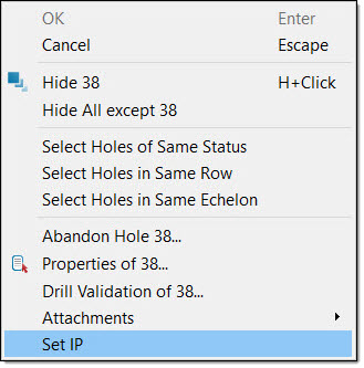
Set an initiation point. You can use either of the following methods to set the initiation points:
-
Select Set IP in the tie-up editor and click the desired hole in the view window.
-
Right-click on the desired hole in the view window and select Set IP from the context menu.
-
If connectors are present in the tie-up then after you set this point, BlastLogic will calculate and display the delay times for the tie-up.
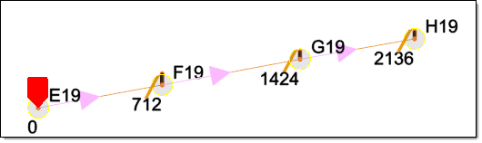
BlastLogic signifies the initiation point with a red pentagon near the hole. To change the initiation point, repeat this steps using a different hole.
Publishing a tie-up
BlastLogic allows you to publish tie-ups as the following types:
-
Draft
You can create a draft tie-up to form initial plans or experiment with different designs. This is the default state of tie-ups when they are first created. You can publish multiple draft tie-ups to share and edit amongst your team. -
Design
A design tie-up is the tie-up design you intend to perform and can be thought of as the tie-up plan. -
Actual
You can create an actual tie-up after the tie-up has been completed. In an actual tie-up, you can record and publish any changes made in the actual tie-up process. This allows you analyse the differences between the design and actual tie-ups.
To publish the tie-up, follow these steps:
-
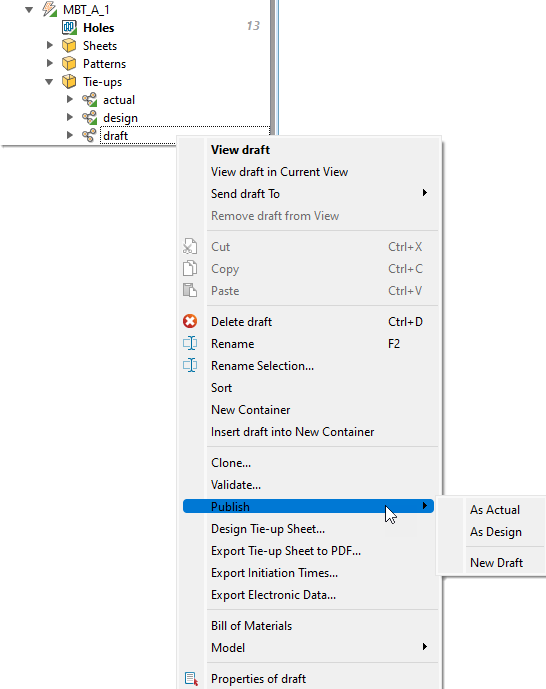
Right click on the tie-up in the Tie-ups folder of the desired blast, in the data explorer. A context menu will appear.
-
Hover over the Publish option on the context menu. A side context menu will appear.
-
Select the desired publishing option. The following options are available:
-
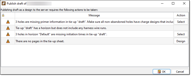
As Actual or As Design
After selecting either of these options, the Publish draft of <blast name> panel will appear. This panel displays a list of any issues with the blast or tie-up that you must address before publishing the tie-up. The panel has the following functionality:-
The issue icon indicates the severity of the issue.
-
For certain issues, BlastLogic will provide a button in the Action column, which you can click to aid you in fixing the issue. Otherwise, you will have to navigate to the issue area and solve the problem.
-
When publishing a tie-up as an actual tie-up, you must record the time when the tie-up was completed in the Completed time drop-down.
 Note:
Note:If the draft you are trying to publish has already been published as a design or actual tie-up, BlastLogic will display the following message in the panel.

To fix this, you can clone the draft by selecting Clone. BlastLogic will automatically change the selected tie-up to the cloned version, allowing you to make any edits and publish the clone as the desired type.
-
-
New Draft
-
Exporting an electronic tie-up
To export an electronic tie-up, follow these steps:
-
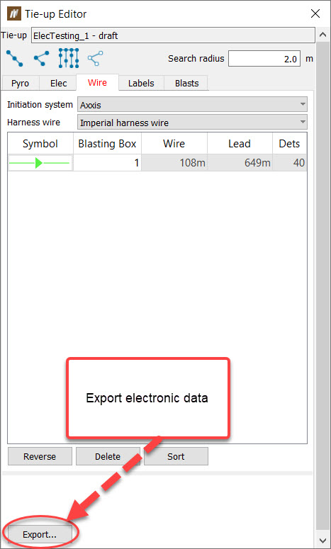
Right click on a tie-up and select Export electronic data.
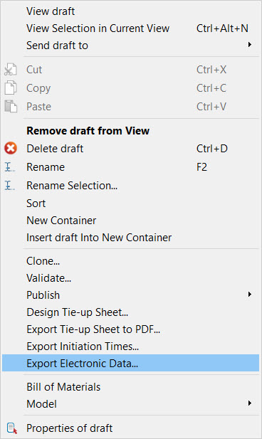
Another way is to click the Export button on the tie-up editors Wire tab.
- Choose the Logger.
-
Choose the format to export to. All electronic initiation systems provide the Export as option PDF. Different electronic initiation systems provide different formats the electronic data can be exported to. For example the DetNet - DigiShot initiation system can export the electronic data to a tagger report.
-
Any issues with the tie-up will be shown at the bottom of the panel. Any issues with icon must be fixed before the electronic data can be exported.
-
Click OK.
Exporting initiation times
To export an electronic tie-up’s initiation times, follow these steps:
-
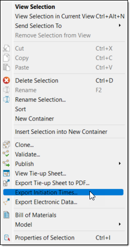
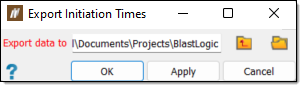
Right-click on a tie-up and select Export Initiation Times....
The Export Initiation Times panel will appear.
-
Specify the location you wish to save the export to in the Export data to field. You can either type the location path into the field or select
 to browse to the location in the file explorer.
 -
Click OK or Apply.
Exporting AXXIS electronic data
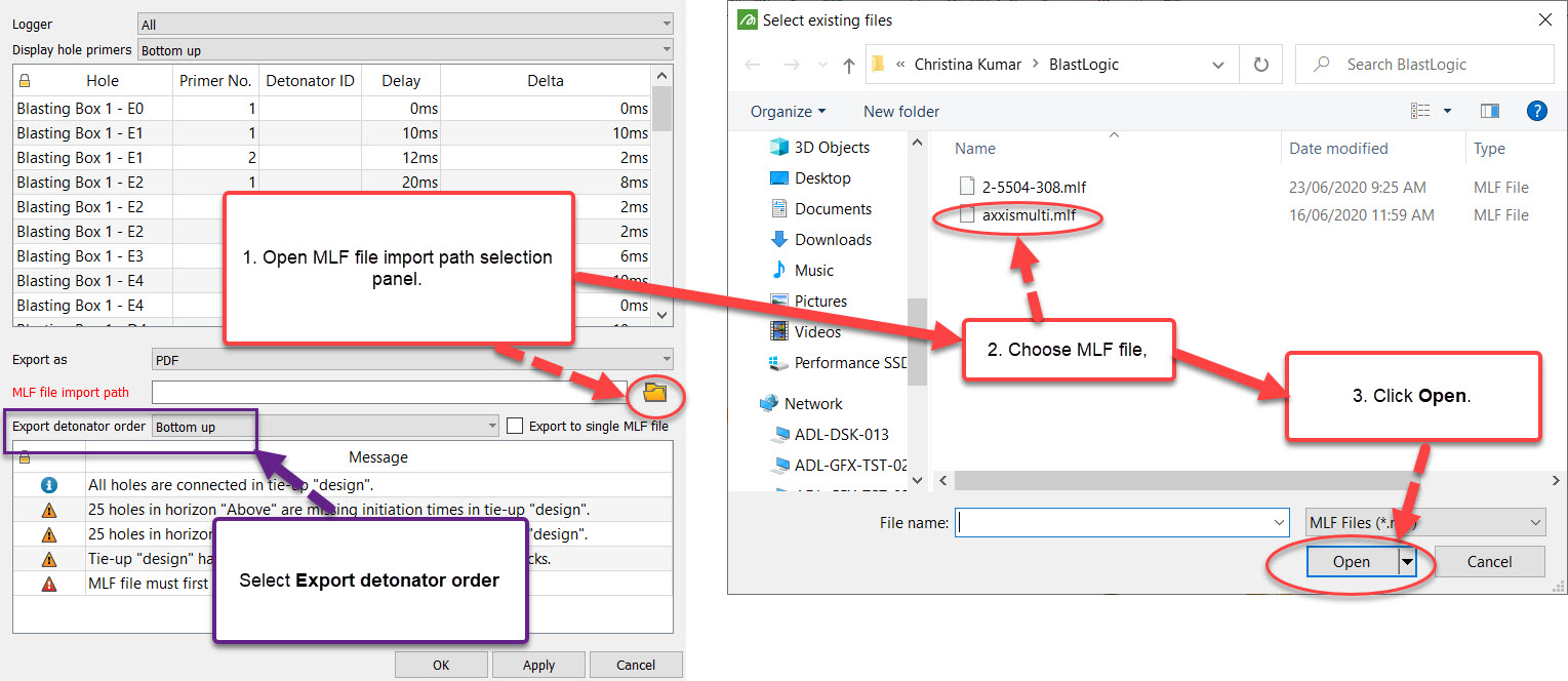
AXXIS export requires importing the MLF file from the logger which corresponds to the tie-up that is being exported. BlastLogic uses this imported MLF file create a new MLF file with added timings and validation to be sent back to the logger.
When Export electronic data is selected on an AXXIS tie-up, the user is required to import actual electronic timings via an MLF file.
To import an MLF file:
-
Click the folder icon on MLF file import path. The MLF import is able to accept multiple files and export to a single file. Note: After importing an MLF file, the table will list the detonator ID from the MLF file next to its corresponding detonator.
-
Select the Export detonator order based on the order of detonators in the MLF file.
-
Select AXXIS MLF from the Export as drop-down list.
-
Check the validation list for any errors in the tie up and click OK.
-
Select an export location for the new MLF file.
Using the Tie-up Editor
The Tie-up Editor has the following tabs:
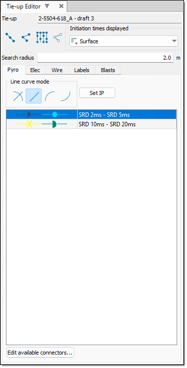
Pyro
The main use of the Pyro tab is to create a pyrotechnic tie-up design. To do this, refer to the Creating a Pyrotechnic Tie-up page.
You can also use this tab in the following ways:
Adding and editing the available pyrotechnic connectors.
In BlastLogic, you can set the available connectors for a given tie-up. This is useful when narrowing down the total list of available connectors to just those that you will use for the tie-up design. To do this, follow these steps:
-
Select the Pyro tab in the tie-up editor.
-
Select Edit available connectors.... The Edit Available Connectors panel will appear. The table displays connector products that are available in the tie-up design.
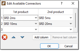
In this panel, you can complete the following tasks:
-
To create a connector, select the product you wish to use from the appropriate cell drop-down.
-
To create a composite connector with two products, add a product using the drop-down in the 2nd product column. Use the Add product column button to create composite connectors with more than two products. For example, to create a composite connector with four products, click the Add product column button twice and then choose the desired products.
-
To delete a connector, select it and click
 .
. -
To remove a product from a connector, select it and press Del.
-
The order of products in the table is the order they will appear in the connector list in the tie-up editor. To re-order the products, select the products you wish to move. Move the products up by clicking
 or down by clicking
  .
. -
You can move one or more products to the very top of the list by selecting the products and clicking
. This is useful for placing the connector products that you will commonly use at the top of the list.
-
- Click OK. The additions or edits are now available in the tie-up editor table.
Changing the pyrotechnic connectors.
In BlastLogic, you can change the product for selected connectors. To do this, follow these steps:
-
Select the connectors you wish to change in the view window. To select the connectors, you must set the selection mode to
 edge selection.Tip!
You can also select a group of connectors by right clicking on a connector and selecting
Note: The connectors can also be selected by right clicking on a connector and choosing the connector product from the Select connectors drop down list.
-
Right click on one of the selected connectors and choose the connector to change to from the Change selected connectors to drop down list. The connectors will be changed and the delay times automatically recalculated, if the initiation point is set.
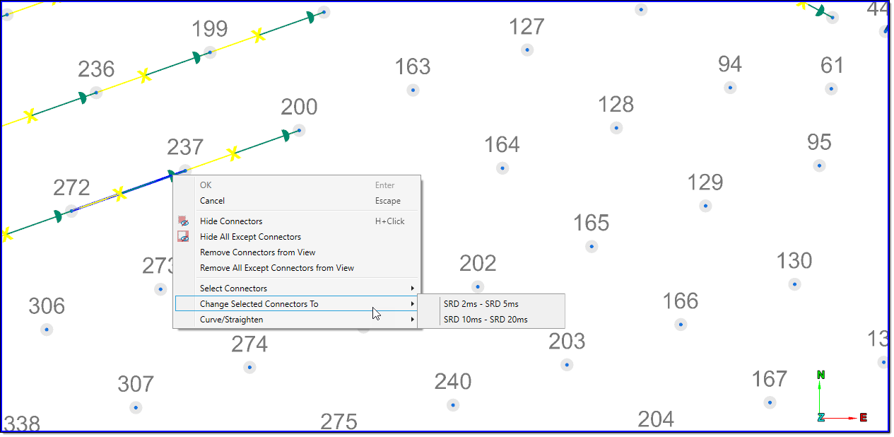
Elec
The main use of the Elec tab is to create an electronic tie-up design. To do this, refer to the Creating an Electronic Tie-up page.
You can also perform the following tasks in this tab:
- Editing timings
- Editing the initiation times for selected holes
- Editing the selected timing relationships
- Disassociating the timing relationships from central control
- Optimising the tie-up timings
- Using reconciled charge and times
Editing timings
The design timing information for the holes in an electronic tie-up can be modified in a table by clicking the Edit timings button.
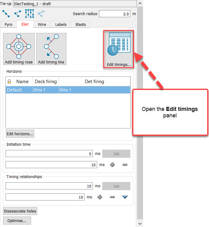
The Edit timings panel shows the initiation time for each hole, and the delay from the preceeding hole or associated timing.
The delay between explosive decks and the delay between detonators can also be adjusted on a hole by hole basis.
To view the timing information for a tie-up with multiple horizons, select the horizon to view from the Horizon drop down list.
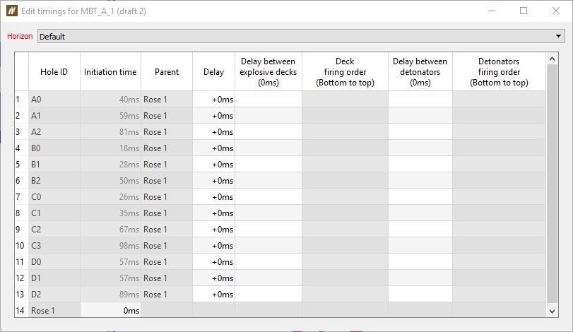
Note: Values that are greyed out are not editable.
Editing the initiation times for selected holes
- Select the holes to change the initiation times for.Note: The selection mode needs to be either in object or point selection mode.
- Enter the initiation time and then click the Set button.
- To adjust the initiation times by a set amount, set the amount in ms to adjust the initiation time by and then use the or buttons.
- To adjust the initiation times in the view window middle click drag on one of the arrows. Dragging to the right increases the initiation times. Dragging to the left decreases the initiation times.
Editing the selected timing relationships
- Select the timing connections to change the timing relationships for.Note: The selection mode needs to be in edge selection mode.
- Enter the timing delay and click the Set button.
- To adjust the outgoing delays by a set amount, set the amount in ms to adjust the timing relationship by and then use the or buttons. All of the subsequent connected holes initiation times will be adjusted accordingly.
- To adjust the timing relationships in the view window middle click drag on one of the arrows.
Disassociating the timing relationships from central control
- Select the holes to remove the timing relationships from.Note: The selection mode needs to be either in object or point selection mode.
- Click Disassociate holes. The initiation times of the holes will remain unchanged, but if you open the Edit timings panel, you will find that the timings of the hole are no longer connected to the central control (the timing rose or timing line).
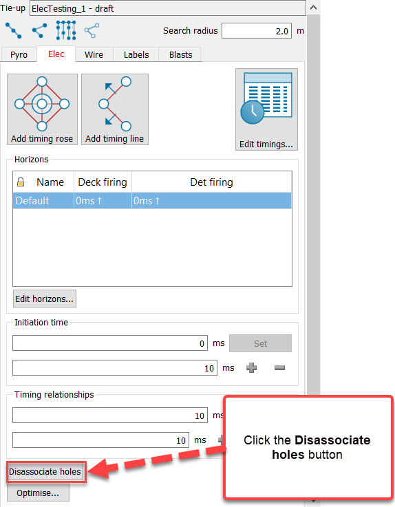
Optimising the tie-up timings
This tab also provides an optimisation tool for electronic tie-ups that adjusts initiation times in order to reduce the number of detonations occurring per timing envelope window to an acceptable level.
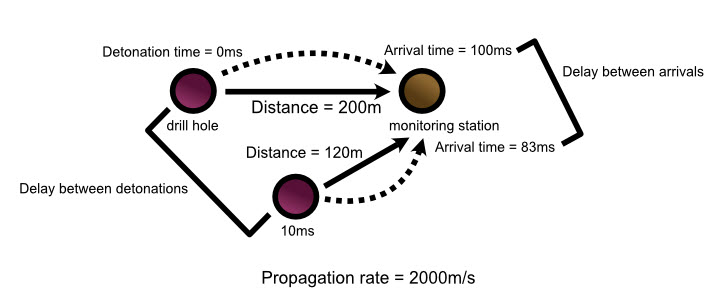
Only an unpublished tie-up can be optimised.
To optimise tie-up timings for a blast:
-
On the Elec tab click the Optimise button.
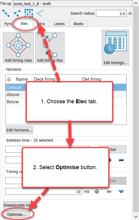
-
Timings can be optimised based on detonation time or arrival time at specified locations. Select one option.
-
If the arrival time method is selected in step 3, set the propagation rate, the minimum delay between arrivals and detonations and extra time allowed. Select locations at which to calculate timings. The tool will attempt to adjust the initiation times such that every detonation and arrival is separated by at least the entered values.
-
If the detonation time option is selected, specify the Minimum delay between detonations. The tool will attempt to adjust the initiation times such that every detonation is separated by at least this value from the immediately preceding and following detonations.
-
Click Optimise.
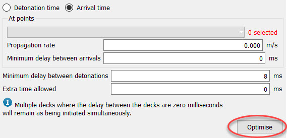
-
Inspect the result using the Timing Envelope and/or Timing Contour tools.
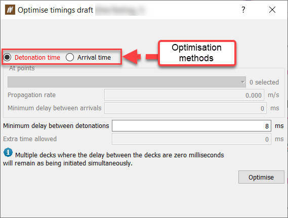
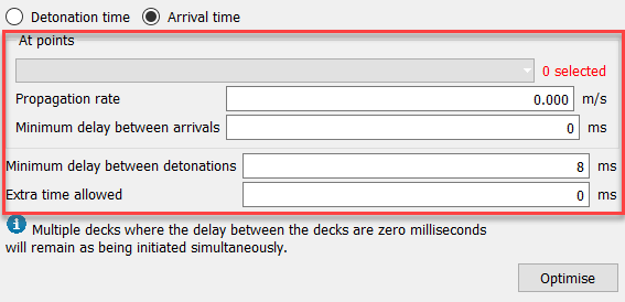
Using reconciled charge and times
The Elec tab provides you with the option to use reconciled charge and times on a tie-up. After creating a design tie-up and assigning these times in the field, you can use this option to create a tie-up based on these actual times. An advantage of this is that you can apply BlastLogic‘s modelling tools to a tie-up with reconciled charge and times so you can model the actual detonator times.
Selecting this option will also override the charge data source to reconciled decks only.
To use the reconciled charge and times option, follow these steps:
-
On the Elec tab, select the Use reconciled charge and times radio button. BlastLogic automatically sets the Initiation times displayed field to All detonators and greys out all of the tab options, except Enter initiation times... and View horizons....
-
Enter the actual initiation timings from the field. Click Enter initiation times to bring up the Initiation Time Data Entry panel. For steps on entering data into this panel, see Initiation Time Data Entry. If you have already entered the initiation times, ignore this step.
BlastLogic will add the entered times to the corresponding holes in the view window.
-
Optionally, view the tie-up horizons by selecting View horizons.... The Horizons for <tie-up name> panel will appear, displaying the horizons of the tie-up.
Wire
The Wire tab allows you to connect harness wire in your tie-up design. You can use harness wire along the surface of a blast to connect electronic detonators to a logger.
To connect harness wire in the tie-up, follow these steps:
-
Select the Wire tab in the tie-up editor.
-
Select the desired attributes from the Primer annotation, Initiation System and Harness wire drop-downs.
Note:You can find a list of the available initiation system and harness wire products in the blast product catalogue. You can find this catalogue by selecting Blast Product Catalogue, from the Setup group, on the Home ribbon. For more information on this catalogue, refer to the Blast product catalogue section of the setup page.
Expand for information on the DetNet - DigiShot initiation system
When using the DetNet - DigiShot initiation system, you can mark holes as special to indicate that they are considered out of sequence. You can use this special tag to mark either an ad hoc and/or a re-drill hole. The special hole contains detonators that were not a part of the plan.
To mark holes as special, select the holes and click Mark as special.
To remove special status from selected holes, select the holes and click Mark as unspecial.
-
Select the desired connection mode.
Expand for more information on the connection modes.
There are four connection modes to select from:
-
Row-by-row
The row-by-row mode ties up all holes inside the selected cursor range.
-
Hole-by-hole
The hole-by-hole mode ties up a series of holes one-by-one.
If you attempt to connect two holes over a distance greater than the connector length, BlastLogic will prevent you from connecting the holes.
-
Auto-fill
The auto-fill mode automatically ties up rows or echelons across a control line template.
-
Dummy hole-by-hole
The dummy hole-by-hole mode ties up a series of hole one-by-one and creates dummy holes when you click in free space. Creating dummy holes allows you more flexibility when creating the shape of the tie-up.
Note:You can only connect harness wire using holes along a line
or hole by hole . You cannot connect harness wire by automatically filling in echelons across a control line .
-
-
Connect the desired holes in the view window by selecting the holes in a sequential order. The connections will appear in the tab table.
Expand for more information on connecting the wire
As you connect the wire between the holes in the view window, BlastLogic displays a line between the consecutively clicked holes. These lines have unique symbols and colours to represent each type of harness wire. You can view details of each connection in the editor table.
The limits for the maximum wire length, maximum lead length, and maximum detonator count per harness wire run are set as properties of the electronic initiation system in the blast product catalogue. If a limit is exceeded, the cell in the harness wire table will be highlighted red. Hover over the cell to see the tool tip error message.
-
Optionally, you can use the following options to adjust the connections:
-
To reverse the direction of a harness wire run, select the harness wire run in the table and click Reverse.
-
To delete a harness wire run, select the harness wire run in the table and click Delete.
-
To sort the harness wire runs in the table, click Sort.
Labels
The Labels tab allows you customise the hole labels in the view window. To do this, follow these steps:
-
Select the Labels tab in the tie-up editor.
-
Select the desired holes in the view window.
-
Select the desired hole horizon from the Horizon drop-down.
-
Select the desired radio button option in the Label section.
-
Edit the desired label properties using the corresponding value fields or sliders.
Blasts
The Blasts tab displays the current blasts in the editor and their associated source data. You can use this tab in the following ways:
Selecting a blast data source
BlastLogic allows you to select the data source you wish to use when creating a tie-up for a blast.
To specify the tie-up data source, follow these steps:
-
Select the Blasts tab in the tie-up editor.
-
In the Current blasts table, select the Source column drop-down. BlastLogic will display the data sources available for the corresponding blast.
-
Select the desired source from the Source drop-down. The drop-down contains four types of sources:
-
Plan
Select the Plan option to create a tie-up using only charge plan data. In this case, no loaded or reconciled data is included in the tie-up. This option is in bold to signify that it is a special data type that you can only access in the tie-up editor and fly rock modelling tool. -
Current
Select the Current option to create a tie-up using reconciled data. If there is no reconciled data, BlastLogic will load the plan data instead (but not any loaded data). This option is in bold to signify that it is a special data type and not a snapshot -
Reference design snapshot
The name of the reference design snapshot will appear as an option in the drop-down. For example, in the image below, the snapshot HP, is in bold to represent that it is the reference design snapshot. Select this option to create a tie-up using the reference design snapshot data.
-
Other snapshots
Any other snapshots related to the blast will also appear in the drop-down. Select the name of the desired snapshot to create a tie-up using that snapshot’s data. These snapshots will not be in bold.
-
Adding blasts to a tie-up.
-
Select the Blasts tab in the tie-up editor.
-
Select the blast you wish to add in the data explorer.
-
Drag the blast from the data explorer into the in the Blasts tab table using the middle mouse button.
Note:Other tie-up objects can also be dragged and dropped into the table using the middle mouse button.
Removing blasts from a tie-up.
-
Select the Blasts tab in the tie-up editor.
-
Select the blast that you wish to remove from the table.
-
Click Remove.
Splitting blasts from a tie-up.
-
Select the Blasts tab in the tie-up editor.
-
Select the blast that is to be split from the table.
-
Click Split. The split tie-up will appear in the data explorer under the Tie-up container for the selected blast.
