Using the Solid Model Viewer

Source file: origin-reserve-models-view.htm

You can view a solid model in the following ways:

  • As a part of a setup together with other setup components (for example, road network, waypoints, and other models). To do so, open the required setup and go to the Viewer tab.

  • Individually as a plain model. To do so, double-click the model in the project explorer.

  • As a part of a schedule result (see Schedule Viewer for more information).

Viewer toolbar

The toolbar in the viewer contains a number of tools that allow you to customise your view and manage the waypoints.

Note:  The tools for managing the road networks are only available when you view your model as a part of a setup.

The viewer toolbar is located above the viewer workspace. 
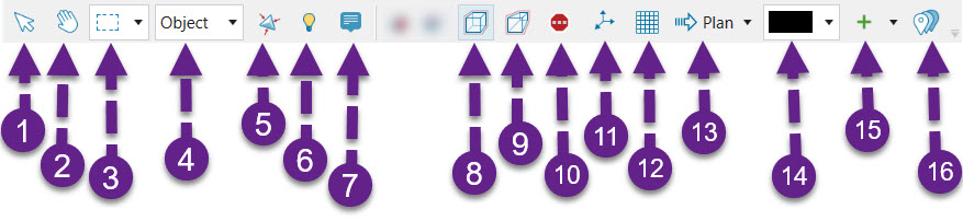
The following table describes each function available in the toolbar.

Interactive Mode
Select the required solids, points, or objects. See Selection type for more information on selecting elements of your setup in the viewer.

Tip:  Hold down Alt while in the interactive selection mode to enable viewer navigation in the hands-free selection mode. See Hands Free Mode for more information.

Tip:  Press Shift to select multiple solid groups.

Hands Free Mode
Zoom (by scrolling), rotate (by left-clicking and dragging), and pan (by middle-clicking) the viewer.
Selection method
Select points, objects, and solids in Rectangle, Polygon, or Lasso mode.

Selection type
Select elements of your setup using the following modes:

  • Block: Select blocks from a block model that you have opened in the Origin Solids viewer.

  • Edge: Select midpoint on the road network.

  • Vertex: Select a point on the road network.

  • Facet: Select non-attributed surfaces or AutoCAD DXF file (.dxf) surfaces.

  • Object: Select solids, equipment, and waypoints.

Toggle Lowlighting Selection
Highlight the model that contains your current selection. Other models will be dimmed.
Eye-dome lighting enabled
Apply shading to the models and objects in the viewer to improve depth perception. This feature is enabled by default. To disable eye-dome lighting, click the toggle button in the Settings panel (Home ribbon > Project group > Settings) or disable it for an individual viewer by clicking the (Eye-dome lighting enabled) button in the viewer toolbar (when you disable the eye-dome lighting directly in the viewer, the icon will change to (Eye-dome lighting disabled)).
Shrink Solids
Shrink solids in the viewer to make their boundaries more visible. To return to the default view, click again. This tool is useful when creating sequences between solids and adding dependencies on a single bench. See Dependencies in Origin Solids and Dependencies in Epoch for more information.
Enable Tooltips
Display all pinned attributes for the solid over which you are currently hovering.

Section Models

Note:  For this function to work in an Origin Solids, you need to drop a block model into your Solids viewer. See Using the Block Model Viewer for more information.

Filter Blocks

Note:  For this function to work in an Origin Solids, you need to drop a block model into your Solids viewer. See Using the Block Model Viewer for more information.

Orthographic Projection
Display all data at the same size regardless of distance.

Perspective Projection
Display data as it would appear if you were looking at it (distant objects will appear smaller).
Toggle Stop Signs
Show and hide stop signs on a road network. Stop signs only appear on road network points where the loaded or unloaded velocity has been set to 0. To change the velocity for a given road network point, enter the Vertex selection type, select the point on the road network, and change the Loaded or Unloaded Velocity to 0 in the Properties panel. Click Save to save the changes you have made. The stop sign on the selected network point will become visible when you toggle the button on.

Note:  The (Toggle Stop Signs) tool is only available when you view your model as a part of a setup.

Set centre of rotation to selected object
Set the viewer’s centre of rotation based on the object you have selected.

Turn on coordinate grid in the view
Display the coordinate grid in your view.

Note:  The coordinate grid is only visible in plan view. To re-enter the plan view, click the button next to the (Turn on coordinate grid in the view).

Plan view
Display your setup in a birds-eye view (by clicking the button), or in either east-west or north-south alignment (by selecting the required direction from the drop-down).
Background colour
Select either the dark (black) or light (light grey) background colour.
Create a waypoint collection

Save the current waypoints in the viewer as a set that can be added to other setups. See Creating a Waypoint Collection for more information.

Note:  This tool is only available when you view your model as a part of a setup.

Waypoint editor

Move, add, and link waypoints in your setup. See Using the Waypoint Editor for more information.

Note:  This tool is only available when you view your model as a part of a setup.

See also:  Evolution display settings

Viewer guidelines

Evolution allows you to view Vulcan layers (linework) by dropping Vulcan design database (.dgd.isis) and Vulcan archive (.arch_d) files into the viewer. This creates guidelines that can help you decide where to make solid cuts (see Solid Cuts for more information). For example, if you have files with grade control polygons (marked out regions that group areas of similar grade), you can drop them into the viewer to identify which regions of the pit or on a certain bench should be scheduled.

When you drop a .dgd.isis or .arch_d file from the file explorer, the Import Layers panel will appear.

Choose which layers to import by selecting the corresponding checkboxes. The selected layers will be imported into Evolution as a single object, unless you select the Import each layer as a separate guideline object checkbox. In that case, Evolution will create an object for each imported layer, enabling you to customise the way each layer is displayed in the viewer.

After applying the required settings, click OK. The layers you selected will be added to the viewer and project explorer as guideline objects. You can apply the imported guideline objects to any Evolution viewer by dragging and dropping them from the project explorer.

Evolution will also create a Guidelines category in the View Manager and list the layers under it.

For each imported layer, you can set a uniform colour and thickness for all lines on that layer. To do so, select the object in the View Manager and click the Apply Uniform Style button.

Next, set the line size and choose the required colour from the colour picker menu. Evolution will reflect your settings in the viewer.

Tip:  Click Revert to Original Style to discard the changes that you have made.

See also:  View Manager in Origin Solids, Cut Solids in Epoch, Importing a Dynamic Solids Pit