Create a DomainMCF Model
The tools for working with DomainMCF are all located on the DomainMCF ribbon tab.

DomainMCF models are generated by bundling your input data and model parameters into processing units called Jobs. When you start a job, the data is uploaded to the Maptek Compute Framework (MCF) for processing in the cloud. The MCF uses machine learning techniques to predict domain boundaries based on the input data and generates a block model. When processing is complete, you can download and view the model in Vulcan GeologyCore.

Get started using DomainMCF modelling by following these steps:
-
Launch the DomainMCF Jobs tool.
The DomainMCF Jobs tool allows you to manage all of your DomainMCF jobs.
To launch the tool, click
 DomainMCF Jobs on the ribbon.
The DomainMCF Jobs panel appears.
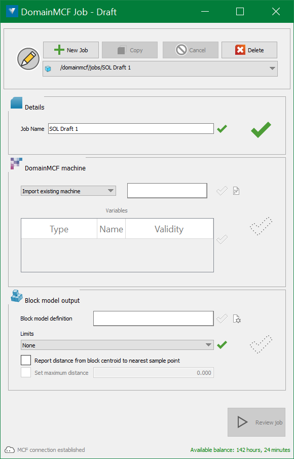
From this panel you can configure and submit new jobs, as well as view summaries of previous jobs.
-
Configure a job.
A DomainMCF job starts off as draft, which means it has not been submitted for processing yet.
The first time you open the DomainMCF Jobs panel, a new draft is created for you ready to fill out. Subsequently, if there are existing jobs in the list, you’ll need to start a new job by clicking
 New Job.
One you have a draft job, you need to supply a set of inputs. Each input has a status icon next to it, as follows:

Input incomplete 
Input complete 
Input complete with warnings 
Input invalid 
Input incompatible Configure the inputs as follows:
-
Optionally, rename the job in the Job Name field.
-
Specify the DomainMCF machine.
DomainMCF Machine files (.dmcf_machine) can now be imported into the DataEngine. These act as file references to a machine file on the file system. A machine file must be imported before it can be dragged into the DomainMCF job panel.
There are two ways to specify DomainMCF machine:
Import existing machine - drag and drop the existing DomainMCF machine into the field. It will load the sample data and its corresponding variables.
Train machine from sample data- specify sample data.
The sample data is a set of points that provide the known domain values. DomainMCF uses these known points to build a model, which is then used to estimate the domain at any given point within the block model extent.
In the Sample Data field, specify either:
-
One or more drillhole databases
 . Vulcan GeologyCore will automatically extract the sample points from the drillholes as interval midpoints. If you specify a database, all drillholes in the databases specified will be used.
 -
A selection-group object containing drillholes as input. This is treated the same way as a drillhole database in which the holes contained are used to extract a point set for modelling.
-
A set of sample points
 . This can be obtained by importing a text file containing comma-separated values (CSV). For more information, please refer Creating a new DomainMCF machine.
You can also generate a set of sample points by running the
 Extract Points option on a drillhole selection. Do this if you wish to model multiple domain fields in the same model, or use grade to help predict domains.
Note: Alternatively, you can drag and drop multiple files onto the Sample Data field, and the combined sample points will automatically be extracted.

-
Select the drillholes you’d like to extract the sample points from.

Selecting drillholes in the project explorer 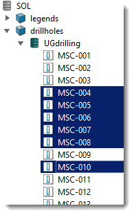
- Shift + Click defines a range
- Ctrl + Click adds/removes a single item
- Ctrl + Shift + Click adds a range
To select all drillholes in a database, click on the drillhole database
 . Hold Ctrl to select multiple databases. If multiple databases are selected, they must have the same schema.
To select a subset of drillholes, use the following controls:
-
Click on a drillhole item
 to start the subset selection.
 -
Hold Shift and click on a drillhole item
 to select the range of items from the last clicked item.
 -
Hold Ctrl and click on a drillhole item
 to add or remove that item from the selection.
 -
Hold Ctrl + Shift and click on a drillhole item to add the range of items from the last clicked item to the selection.
Tip: Type into the Filter field at the top of the project explorer to display only objects matching the given string.

Selecting drillholes in the view window 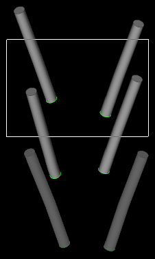
- Shift + Click adds drillholes
- Ctrl + Click removes drillholes
To select all drillholes in the view, press Ctrl + A.
To select a subset of drillholes, use the following controls:
-
In the selection toolbar located at the top of the project explorer, make sure the selection mode is set to objects
 . If selecting a region, choose Rectangle
  , Polygonal Lasso
 or Freehand
  Selection Mode.
 -
Hold Shift and draw a region to add multiple drillholes within a region.
-
Hold Ctrl and draw a region to remove multiple drillholes within a region.
-
Hold Shift and click on a drillhole to add a single drillhole.
-
Hold Ctrl and click on a drillhole to remove a single drillhole.
-
On the ribbon, go to DomainMCF > Sample Points >
 Extract.
The Extract Points panel appears.
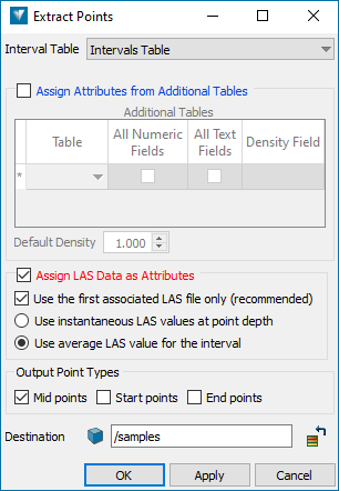
-
Choose the drillhole database table defining the intervals from the Interval Table drop-down. The table should usually be Intervals Table.
-
If you wish to add assay data values as attributes to the points, select the Assign Attributes from Additional Tables checkbox. This produces a mass-weighted average for the numeric fields and a mass-weighted majority for the string values pertaining to each interval, which will then be assigned to the point(s) created for that interval.
For each assay table of interest, specify the table name and the density/specific-gravity field on that table (if available). The latter is used for the mass-weight calculation. Also, specify a default density value which will be used if there is no density value assayed (either no value entered on a record or no density field available). Optionally, you may also choose to extract numeric fields only, text fields only, or both from the record.
Note: DomainMCF requires complete records for modelling. Ensure that any additional domains or grade are fully sampled.
-
Optionally, you can also add downhole geophysical log data values (from LAS files) as attributes to the points created. The Assign LAS Data as Attributes option is enabled only if there is any LAS data associated with the selected holes.
-
Use the first associated LAS file only: Drillholes may have more than one associated LAS file. Choose this option to use the first association only. If there is more than one file association, it is possible that the same curve name exists in both files. So, if multiple associated files are used, the common values will be taken on a first come basis and will be ignored when subsequently found.
-
Instantaneous LAS values: This will be determined at the depth of the created points - this way the top, middle, or bottom interval points could have different values for their LAS attributes.
-
Average LAS values: This will be calculated from all of the LAS data points covered by the interval depth range - this way the top, middle, or bottom interval points will all carry identical LAS attribute values, which are the weighted average for the interval.
-
-
Under Output Point Types, select the point types you’d like to extract and include in the sample point set. The default and recommended point type is Mid points.
-
Optionally change the output destination container to store the sample points. The default destination is the samples container
 .
. -
Click OK or Apply to extract the points.
You can view the generated sample points by dragging them from the project explorer into a view window.

-
-
Combine multiple point sets

 .
.You can correlate and combine multiple sample points by running the option
 Correlate and Combine points. Use this option when you have multiple point sets that you wish to upload to the DomainMCF.
-
On the ribbon, go to DomainMCF > Sample Points >
 Combine.
The Correlate and Combine Points panel appears.
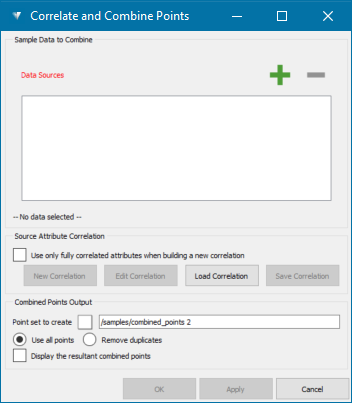
-
Add sample data sources from which the combined point set is to be created.
To add samples, select the data sets from the samples container
 in the project explorer and drag it on to the Data Sources area, or click on
  Add button on the panel. Use Ctrl + Click to select multiple samples.
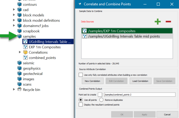
Important! At least two data sources must be selected. The order of the selection is important because the data source sitting at the top of the selection (first data source coloured in green) will define the structure of the resultant point set. The attributes of the first data source will define the initial list of attributes to be added to the combined point set. The list may be changed and/or added to, but it is better to use the data set with the most number of attributes as the first data source.
-
Set up a new correlation to link the fields between the point sets. You can create a new correlation or load an existing correlation. Optionally, you can select the option Use only fully correlated attributes when building a new correlation to use only those attributes for which there is a representative in each source.
-
New Correlation - Use this option to create a new correlation for the selected sample data sets.
-
Edit Correlation - Use this option to edit the current correlation for the selected sample data sets.
-
Load Correlation - Use this option to load an existing correlation which matches, or can be made to match, the selected sample data sets.
-
Save Correlation - Use this option to save the current correlation for future use.
Note: Any fields that have different names can be manually matched up. However, validity warnings will be displayed if data types (eg. text and integer) are found for the data sources.
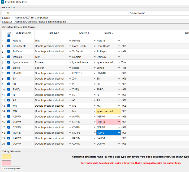
- Yellow warning indicates differing but compatible data types (eg. a numeric can be saved into a text field)
- Red warning indicates a data incompatibility (eg. trying to save text into a numeric field)
ddd -
-
Under Combined Points Output, set the name of the resultant point set to be created in the Point set to create field. The default naming convention is /samples/combined_points, where samples is the output destination container to store the combined sample point.
-
Choose whether or not to remove duplicate points from the resultant point set.
Use all points - Select this option to use all points in the resultant point set irrespective of whether the points are duplicated or not.
Remove duplicates - Select this option to remove the duplicated points in the resultant point set.
-
Click OK or Apply to generate the resultant point file that can be uploaded to the DomainMCF.
-
-
-
Specify a block model definition.
A block model definition contains the physical configuration of the desired block model, including its origin, extent, orientation and block size constraints, as well as the names of the variables you want to model.
You can either supply an existing block model definition, or let Vulcan GeologyCore generate one for you based on your sample data.
-
To use an existing block model definition
 , drag it from the project explorer into the Block Model Definition field. Block model definitions are stored in the block model definitions container
  by default. To import a block model definition from a Vulcan block model definition file (*.bdf), go to Home > Data >
  Import.
 -
To generate a block model definition from your sample data, simply click
 to the right of the Block Model Definition field. The generated block model definition will be created in the block model definitions container
  , named after the job name, and suffixed with “BDF”.
Note: DomainMCF accepts regular block models (having all blocks the same size), and sub-blocked block models with a parent to sub-block ratio of ½, ¼, ⅛ or 1/16. Imported block model definitions will be rounded to the nearest size compatible with DomainMCF.Whether you supply an existing definition or generate one, you can inspect and modify the parameters by clicking
 to the right of the Block Model Definition field.
 Expand for detailed instructions on how to modify the block model definition.
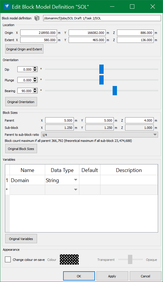
You can change the block model parameters as follows:
-
Under Location, define the location of the block model in space, in terms of the following:
-
Origin X, Y, Z—the reference location from which the extent of the block model is defined.
-
Extent X, Y, Z—the volume of space limiting the size of the block model.
Click Original Origin and Extent to reset the fields to their initial value.
-
-
Under Orientation, define the angular measurements expressing the orientation of the block model in space, in terms of Dip, Plunge and Bearing.
Click Original Orientation to reset the fields to their initial value.
-
Under Block Sizes, configure constraints on the size of individual blocks within the resulting model. The extent must be an exact multiple of the block size.
-
Parent X, Y, Z—the maximum size of a parent block in each dimension.
-
Sub-block X, Y, Z—the minimum size of a sub-block in each dimension. Configure the sub-block size by setting the Parent to sub-block ratio. Choose from the following values: ½, ¼, ⅛, 1/16 or Make all blocks the same size.
Click Original Block Sizes to reset the fields to their initial value.
-
-
Under Variables, specify the variables to be modelled. At a minimum, you will want to specify Domain as a variable to model.
Click Original Variables to reset the variable list to the initial list.
-
Under Appearance, select the Change colour on save checkbox to apply a specific colour and translucency to the block model definition object. This affects the visualisation of the object when viewed in a view window.
-
Click OK or Apply to update the block model definition.
-
-
Specify limits to constrain the size and shape of the realised block model. These are optional surfaces or a solid file that are used to limit the resulting block model to a specific region in space. This is useful, for example, to prevent predicting points in the sky (by supplying a surface representing the topography), or to restrict modelling to a certain subregion of the block model extent.
Select from the drop-drop list either:
-
None (default) — doesn't specify any limit.
-
Surfaces — represents top and bottom topographic surfaces. Drag and drop the surfaces into the top and bottom fields. The realised block model will be confined to the region between the two surfaces.
-
Solid — the realised block model will be confined to the region inside the solid. Drag and drop it into the solid field.
Specifying a convex hull is a good way of limiting the generated model to the volume covered by the sample data.
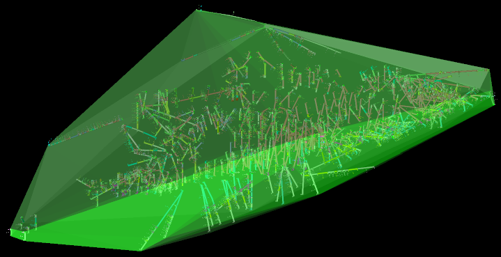
 Expand for detailed steps on how to generate a convex hull.
-
Select your sample data. This could be sample points, drillholes, or any other data type.
-
On the ribbon, select DomainMCF > DomainMCF Modelling >
 Hull.
Hull.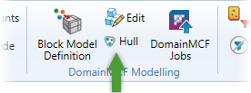
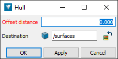
The Hull panel appears.
-
In the Offset distance field, optionally enter a positive distance to offset the hull from the data.
-
Click OK or Apply.
The convex hull is generated as a surface
 in the specified destination folder
  (/surfaces by default).
-
-
-
Optionally, you can choose to select these two options to configure Block model output.
-
Report distance from block centroid to nearest sample point — If you select this checkbox, the block model will include a sample point distance attribute for each block. Note that this option can increase the time taken for the job to run.
-
Set maximum distance — You can select this option if the Report distance from block centroid to nearest sample point checkbox is selected. If selected, the sample point distance will be calculated up to the specified value. If not selected, an exact distance will be calculated for each predicted block. Specifying a lower value can reduce the computation time.
-
Once all the inputs are valid
 , the Review Job button becomes enabled, meaning you can check if the job is ready for processing or not.
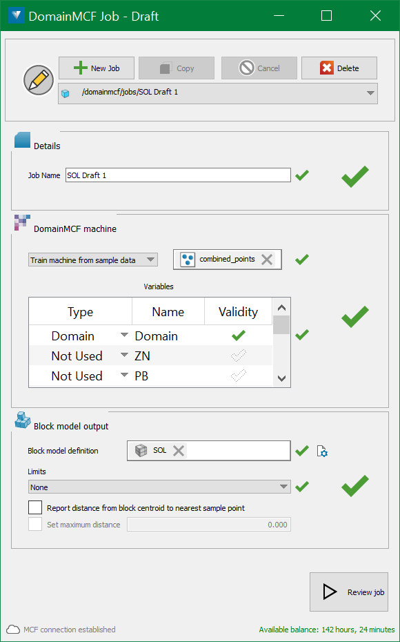
Once Review Job is run, the following panel is displayed which gives information about the DomainMCF machine and Block model output to be processed.
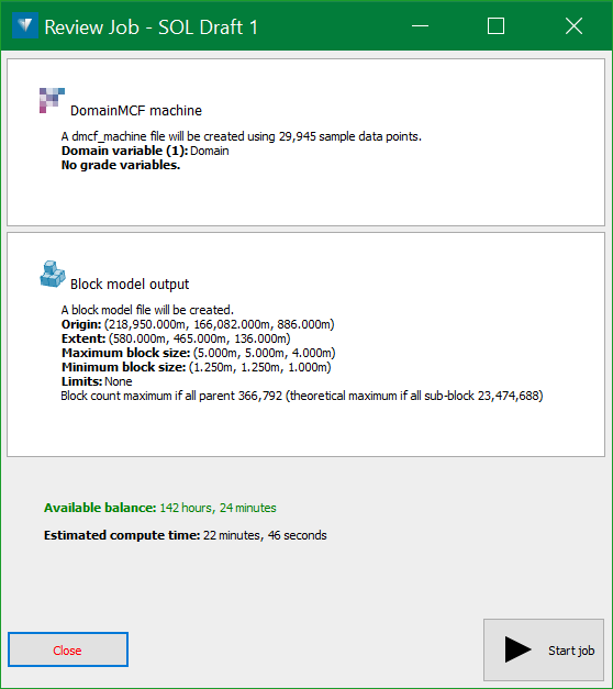
Note the Available balance of processing time you have left, and the Estimated compute time for the job.
-
-
Run the job.
To submit your job for processing, click Start Job.
Your job begins uploading to the MCF server for processing, and the DomainMCF Job tool displays a summary of the job details.
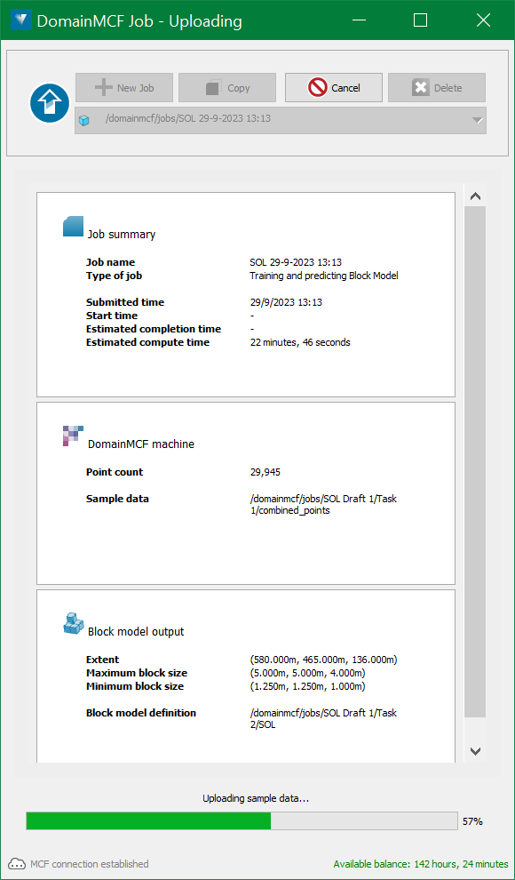
-
Download and view the result.
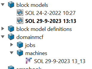
When processing is complete, the resulting block model will be automatically downloaded and will be stored in the block models container
 .
.
You can click View Block Model to load the block model into a new view window.
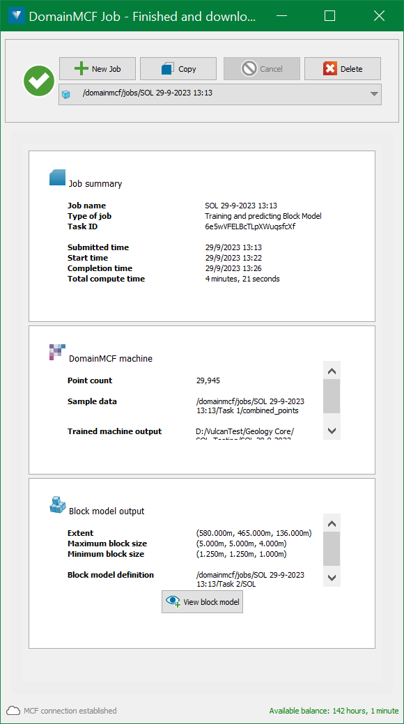
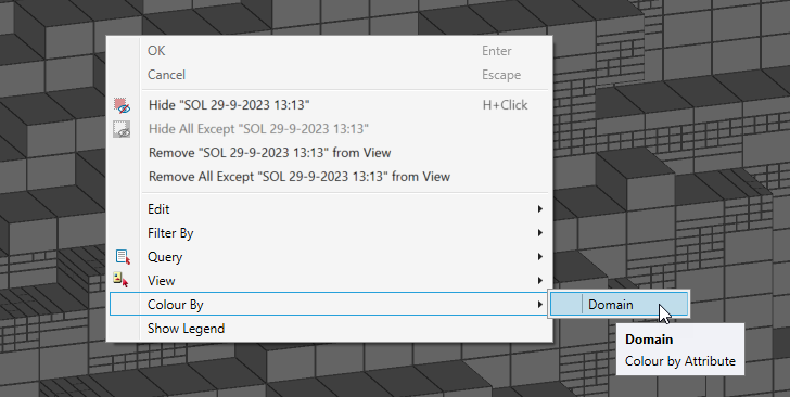
To colour the block model, right-click on it in the view, and in the context menu select Colour By > [Domain Attribute].

|
Create a Stratigraphic Model
|