Create an Implicit Model
Implicit modelling is an approach to spatial modelling in which the distribution of a target variable is calculated by a mathematical function that is derived directly from the underlying data. The solution of the function depends on user-defined parameters. This modelling approach can be applied to discrete variables such as lithology, or to continuous variables such as assay measurements.
The ![]() Implicit Model tool allows you to generate implicit models and surfaces from drillhole and interpretive CAD data, controlled with anisotropic information (via ellipsoids) and other parameters.
Implicit Model tool allows you to generate implicit models and surfaces from drillhole and interpretive CAD data, controlled with anisotropic information (via ellipsoids) and other parameters.
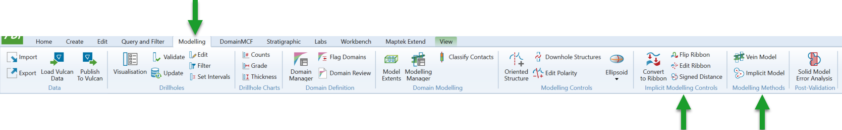
The implicit modelling tools are located on the Modelling ribbon tab, in the Modelling Methods and Implicit Modelling Controls group.
Follow these steps to create an implicit model:
-
Launch the Implicit Model tool.
On the ribbon, navigate to Modelling > Modelling Methods >
 Implicit Model.
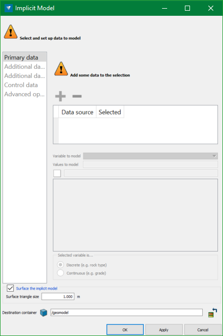
The Implicit Model panel appears.
-
Specify the data to model.
There are two types of data you can provide for implicit modelling:
-
Attributed value data
This includes drillholes, composites or sample data, which come with attributes representing values to be modelled (such as domain codes). -
Interpretive topology data
This includes ribbons and any other kind of geometric data such as lines or polygons. The raw points from this kind of data are used to constrain the model so that the points sit on the surface. Ribbons further control the model so that the sides match up with model, i.e. inside with inside and outside with outside, allowing for complex relationships to be modelled. Expand for how to create ribbons.
To create ribbons:
-
Select any number of lines
 and polygons
  . You can create these using the tools on the Create ribbon menu.
 -
Navigate to Modelling > Implicit Modelling >
 Convert to Ribbon.
Each selected object is converted into a ribbon
 or ribbon loop
  .
.-
Click
 Flip Ribbon to flip the orientation of selected ribbons.
 -
Click
 Edit Ribbon to dynamically change the orientation, position, or width of selected ribbons in the view.
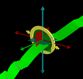
-
See Ribbons for more detailed information on ribbons.
-
Because attributed data comes in various formats, you can only specify one kind of attributed data at a time—for example, a single drillhole database or several sample data sets. Set one kind of attributed data on the Primary data tab, and then set other kinds of attribute data on the Additional data 1 and Additional data 2 tabs as required. You can, however, specify any number or kind of raw geometric data in any of these tabs.
Follow these steps to select and set up data to model:
-
Start on the Primary data tab.
-
In the Selection list, specify either or both of the following:
-
One kind of attributed data you want to model, such as drillholes
 or sample data
  .
. -
Any number of interpretive objects, such as ribbons
, lines , polygons , points or surfaces  .
.
-
-
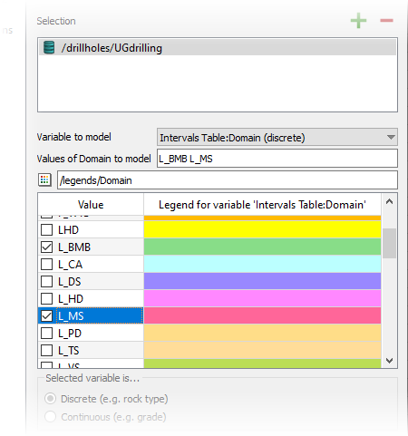
For attributed data, select the variable you want to model from the Variable to model drop-down.
The variable will be a table and field for drillhole data, or a named attributed for other attributed data types. To model drillhole domains, select Intervals Table:Domain.
-
For attributed data, specify the values you want to model. Either:
-
Type the names of the values in the Values of <variable> to model field.
-
If there is a compatible legend for the variable you want to model, make sure it is specified under Legend. Then, select the checkbox for the values from the Value column.
-
-
Specify whether the variable is to be interpreted as discrete or continuous.
Under Selected variable is..., select either Discrete or Continuous as appropriate.
-
To supply more kinds of attributed data, such as drillholes from a second database, switch to the Additional data 1 tab (and if necessary, the Additional data 2 tab) and repeat steps b–e.
-
-
Set up control data.
Implicit models can be constrained and controlled in many ways. Step 2 above described adding interpretive data as a way of controlling the model. Switch to the Control data tab for other methods of controlling the model, described below.
Anisotropic control
Ellipsoids provide localised anisotropic control. Use them to orient the model along a structural trend, or to bridge gaps which may appear in sparse data.
In the Anisotropic control list, specify one or more ellipsoids
 . It is recommended that a few ellipsoids are used initially, adding more later only if required.Expand to see instructions on how to create an ellipsoid.
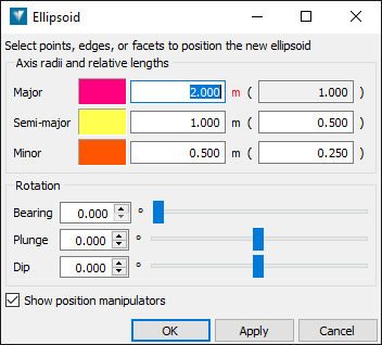
To create an ellipsoid:
-
On the ribbon, navigate to Modelling > Implicit Modelling >
 Ellipsoid.
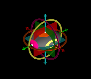
The Ellipsoid panel appears and an ellipsoid appears in the view at the centre of rotation.
-
Configure the ellipsoid by changing values in the panel, or by using the ellipsoid’s dynamic manipulators in the view.
Tip: Click and hold the middle mouse button on an ellipsoid manipulator or the ellipsoid itself to change the ellipsoid’s size, shape, or position.
-
Click OK or Apply to create the ellipsoid.
The ellipsoid
is created and saved into the geomodel standard container  .
.
See more detailed information about creating and editing ellipsoids in Ellipsoids.
Drillhole controls
You can use the following drillhole controls to modify the behaviour of the implicit model around drillholes:
-
Use downhole survey data for control
Select this checkbox to add drillhole toe and collar points, as well as survey depths, that are not within matching logged intervals, as additional control points. -
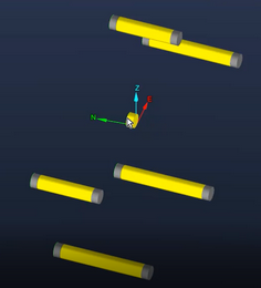
Drillhole ends
Under Drillhole ends, you can control the modelling behaviour where intervals of the target value occur at the top or the bottom of a drillhole. This is to account for cases where the drillhole data is incomplete, in which case you might like to ignore the interval.
Choose how to classify matching intervals occurring at the top or the bottom of the hole, either as:
-
on the surface boundary—i.e. make the model honour the interval.
-
inside the surface—i.e. ignore the interval.
The diagram on the right will update to indicate the effect of your choice.
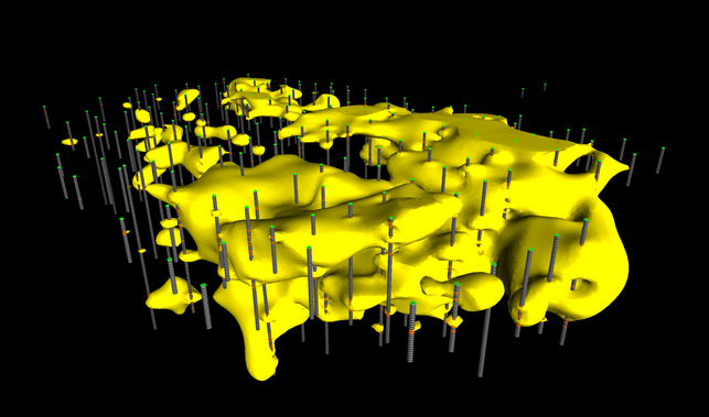
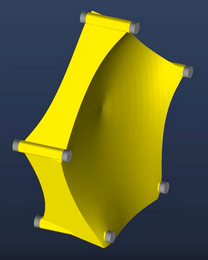
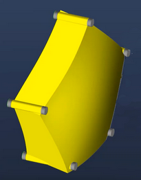
Consider the example below. The first frame shows several drillholes, with the target interval coloured yellow. The drillhole in the centre has a single, short interval which may be incomplete. The second frame shows the resulting model if the interval is specified as being on the surface boundary. The model pinches in to honour the data exactly. The third frame shows the resulting model if the interval is specified as being inside the surface, in which case it is ignored, and the surface is modelled on the trending drillhole intervals.
-
-
Add drillhole contact offset points
Select this checkbox to add extra points at the drillhole unit contact to provide better local control of the model in these areas. The orientation of the extra points is determined by the hole direction when there is no anisotropic control in use, or by the local ellipsoid orientation when the anisotropic control is used.
Extent infill points
Implicit modelling occasionally suffers from balloon or trumpet-shaped “blowouts” where the model is not sufficiently constrained by the data being modelled.
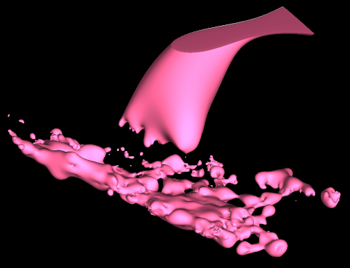
Extent infill points are extra points added around the outside of the data to control the model.
To add infill points:
-
Select the Add extent infill points checkbox.
-
In the Range From and To fields, specify the distance range from the data within which infill points should be added. Choose a smaller distance that’s close to the data, but no so close as to stop interpolation between the data points. The larger this range, the more points will be added to control the model, but the total modelling time will increase.
-
In the Spacing field, specify the average spacing between the infill points. The closer the infill points are, the better the control, but the total modelling time will increase.
Tip: To view the infill points generated, on the Advanced options tab, select the Save signed distance data points checkbox. The infill points will be included in the data points object saved in the model container.
Surface controls
Control the generation of the surface with the following options:
-
Create closed solid surfaces
Select this checkbox to force the model to close off around the model extents. -
Surface envelope
By default the extent of the implicit surface is based on the extent of the selected data. Optionally use this object to add to the modelling extend as well as defining a limiting envelope for the surface.Note: The limiting solid must have be valid with the normals
A unit vector associated with every face of a surface, which is used to encode the sense of "up/down", "inside/outside", or "front/back". Some tools require that surfaces have consistent normals, i.e. adjacent faces need to be all up or down (not both), inside or outside (not both), or front or back (not both). facing inwards. Most solids created in Vulcan GeologyCore will be valid, but imported solids may not be. Check surface validity using the validation tool, and fix normals using the fix surface tool. -
Distance to nearest data point
Optionally limit the extent of the surface to no more than this distance away from any data point.
-
-
Configure advanced options.
Switch to the Advanced tab to configure advanced options relating to modelling performance and evaluation.
-
Domain overlap ratio
Increasing the overlap ratio may provide a tidier result by reducing large artifacts, at the expense of longer modelling time. Even small increments will have a significant effect on modelling time. It is recommended that small changes are made first to compare the results. -
Surfacing performance
Multithreading is a way of taking advantage of multiple processors to reduce processing times, but due to the modelling algorithm implementation, it may be at the cost of robustness. Choose between the following threading approaches:-
Single threaded—A single thread is used. This is the most robust method but takes the longest time.
-
Multithreaded large regions—Use multiple threads, dividing the surfacing into large regions that can be processed in parallel.
-
Multithreaded small regions—Use multiple threads, dividing the surfacing into many smaller regions. Potentially the fastest method, but also potentially the least robust, with holes potentially forming in the surface. This method is useful for quickly examining a model.
-
-
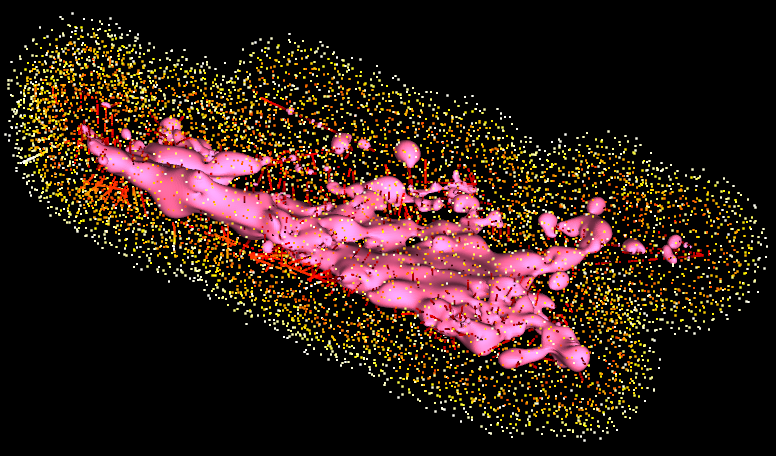
Save signed distance data points
Select this checkbox to save the signed distance data points used to create the implicit model. This will include points from supplied data as well as any generated infill points. The points will be saved in the model container. You can inspect the signed distances using the Point Attributes tool. Distances greater than zero are points outside the solid. Distances less than zero are points inside the solid.
-
-
Configure the surface options and destination container.
Surfacing the model
By default, a surface representation of the implicit model will be generated at a defined resolution. It may be useful when troubleshooting to only generate the underlying implicit model without creating the surface.
-
If you want to generate the surface, ensure the Surface the implicit model checkbox is selected. Surface triangle size specifies the nominal spacing between surface model points, and therefore the resolution of the model. A smaller triangle size will result in a more detailed model that models smaller structures more accurately, but is more expensive in terms of processing time and storage requirements.
-
If you only want to generate the underlying implicit model, clear the Surface the implicit model checkbox.
Destination
By default, the implicit modelling tool will store all output objects associated with a single run of the tool in a single output container
 named after your input data type and selected variable and value combination. This container is stored in the geomodel standard container by default.
You can specify a different location for the output container by dragging a container from the project explorer onto the Destination field—the name of the output container will be preserved.
-
-
Generate the model.
Click OK or Apply to generate the implicit model.
A summary of your input data and selected options is displayed in the report window, including information if the model was not able to be generated.
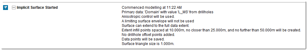
When modelling is complete, another summary of the modelling is displayed in the report window. To view all the outputs in a new view window, right-click on the output container
in the report, and select View <Output container name> from the context menu. To view only the surface, right-click on the surface in the report, and select View <Surface name> from the context menu.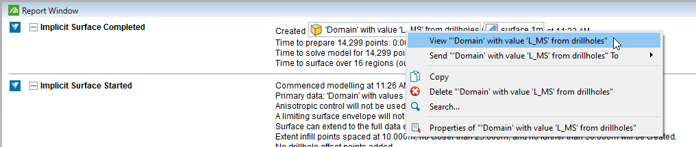
The underlying implicit model object
 is saved in the output container along with any other output objects. The model surface , if generated, is linked to its implicit model object. You can see which surfaces are associated with a model by selecting the implicit model object in the project explorer—any surface generated from the model will be highlighted in light blue.
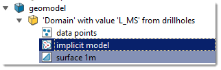
Remodelling
You can regenerate an implicit model using different parameters. There are a few ways to do this:
-
Keep the Implicit Model panel up by pressing Apply instead of OK.
-
Right-click on the implicit model object
, and select Re-create Implicit Model... from the context menu.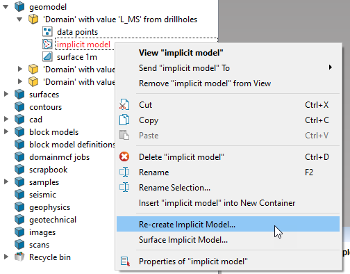
-
Right-click on a model surface
, and select Remodel... from the context menu.
Configure the model inputs and parameters on the panel as desired, and then click OK or Apply.
If you attempt to re-generate an implicit model with the same destination as an existing model, you will be prompted whether you want to replace the existing model, or insert a new model.
Resurfacing
You can also generate or regenerate the surface for the implicit model without having to regenerate the implicit model. This is useful if you did not initially generate the surface, or if you want to regenerate the surface at a different resolution. There are two ways to do this:
-
Right-click on the implicit model object
, and select Surface Implicit Model... from the context menu. -
Right-click on the model surface
, and select Resurface... from the context menu.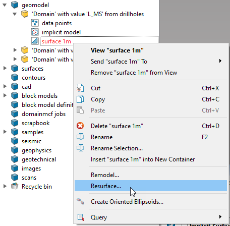 Expand for detailed instructions on resurfacing an implict model.
When you choose to surface or resurface an implicit model, a panel appears showing the surfacing options:
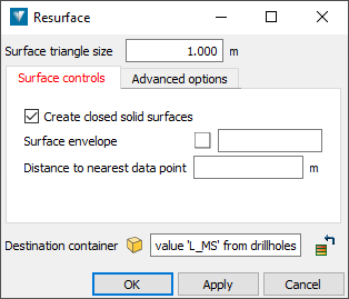
Change the options as desired and then click OK or Apply.
If you did not choose a different destination, you will be prompted whether you wish to replace the existing surface, or insert a new surface.
-
|
Create a DomainMCF Model
|