Importing Data
Note: Your role must have the Manage Surface Uploads permission enabled to import data. See Site Settings > Roles for more information.
The surface model represented in GeoSpatial Manager is a combined model derived from many individual source surfaces. Each source surface in turn may have been derived from one or many sources. The ![]() Import tool allows you to upload source surface files, which GeoSpatial Manager then automatically merges into the combined surface. The tool also allows you to upload GeoTIFF image files associated with the surface model.
Import tool allows you to upload source surface files, which GeoSpatial Manager then automatically merges into the combined surface. The tool also allows you to upload GeoTIFF image files associated with the surface model.
Note: GeoSpatial Manager needs to be configured for use with a Mapbox account before images can be uploaded. See Surface Imagery for more information.
Tip: When initially importing multiple historical surfaces, it is recommended practice to import the oldest surface first, then check the visualisation before importing the remaining surfaces.
To upload surfaces or images, follow these steps:
-
Click
 Import located at the top of the page. A page will display that allows you to import files.
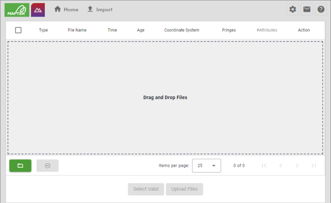
-
Specify one or more files for upload. There are two ways to do this, as follows:
- Drag files directly from Windows File Explorer and drop them into the area in the middle of the page labelled Drag and Drop Files.
- Click
 . In the file browser that opens, select the files you want to import, then click Open.
NoteSurface files must be one of the following formats:
- Vulcan Triangulation file (
.00t) - Maptek Object file (
.maptekobj). Maptek Object files must contain exactly one surface. - AutoCAD DXF file (
.dxf) - Wavefront OBJ (
.obj)
Images must be GeoTIFF files (.tif, .tiff) that correctly georeference the surface model.
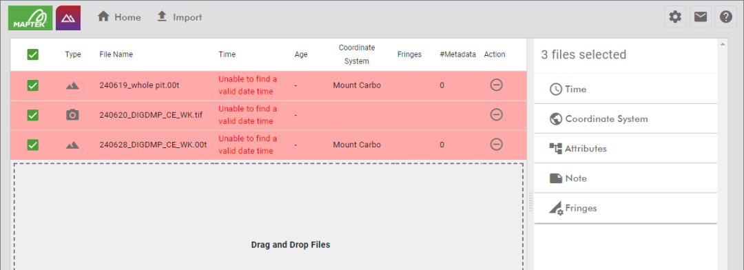
After you have specified the files, they appear in a list with each new file highlighted in red. The red highlight indicates that GeoSpatial Manager needs more information about the file before it can be imported, explained in the next step.
-
Configure the details of each file.
To the right of the file list are several tabs where you can configure the details of selected files.
Select one or more files by making sure their checkboxes are selected in the file list. Then, configure each detail section on the right such as Time or Coordinate System by making sure the section is expanded and filling out the fields as necessary. Required fields in each section are marked with an asterisk (*). These fields must be set before you can proceed with surface import. When you have configured all required fields, the Upload Files button will become enabled.
 Time
TimeGeoSpatial Manager needs to know the date and time that each surface or image represents to ensure they appear in the correct chronological order. If your surface or image filenames follow a systematic naming scheme incorporating the date and time, you can configure GeoSpatial Manager to automatically parse the date and time from the filename. Otherwise, you can set the date and time (or just the time component) manually.
 Expand for detailed instructions on setting the date and time of surfaces.
To set the date and time for selected files, make sure the
Time tab on the right is expanded.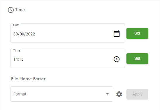
Setting the date and time manually
-
To set the date manually, click the
 button in the Date field. In the calendar tool that appears, select the date corresponding to the selected files, then click
  to apply the date.
 -
To set the time manually, click the
button in the Time field. In the panel that appears, select the time for the selected files in 24-hour clock format. Click to apply the time.
Parsing filenames automatically
To parse filenames for the date/time, you need to specify or configure the date/time parser.
-
To use an existing filename parser, select it from the File Name Parser drop-down, and press Apply.
-
To configure a new date/time parser, click the
 button to the right of the File Name Parser drop-down. In the Date Time Parsers panel that appears, you can create and configure any number of named date/time parsing formats.
Note: You must be assigned a role that has the Edit Settings permission enabled to configure date/time parsers.
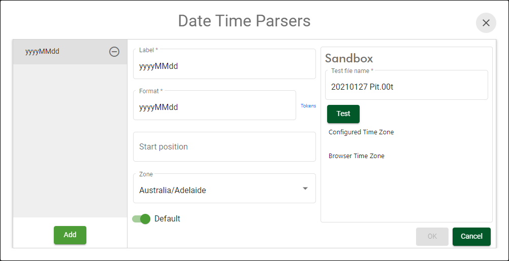
To create a new parsing format, click
 , then configure the format as detailed below.
Label Enter a unique name for the parsing format.
Format Enter the date/time format corresponding to the file naming scheme. You need to specify the format in terms of a sequence of tokens that represent the expected date or time component, or other tokens such as separators. The most common tokens are shown in the table below.
Token Description Example yyyy Year 2023 MM Month as a two-digit padded number 09 dd Day of the month as a two-digit padded number 30 HH Hour in 24-hour time as a two-digit padded number 14 mm Minutes as a two-digit padded number 15 ss Seconds as a two-digit padded number 00 As an example, the date/time 2:15 pm, September 30, 2023 might be represented in a filename using the ISO 8601 format as 2023-09-30T141500. A format that can correctly parse such a string would be yyyy-MM-ddTHHmmss.
Click the Tokens link to the right of the Format field for a complete listing of all possible tokens.
Start position Optionally specify the position within the filename to start searching for the date/time from. A positive number will trim N characters from the beginning, while a negative number will trim N characters from the end.
Zone Select the time zone applicable to interpreted dates and times.
Default Enable this option to set the parsing format to the default. This means you won’t need to manually select the file format parser each time you import a surface.
Sandbox As you define the format, you can test the result of applying the format to a filename in the Sandbox area on the right-hand side of the panel. Enter a filename in the Test file name field, and click
 .
.
 Coordinate System
GeoSpatial Manager needs to know the coordinate system that each surface is in to correctly geolocate it. To set the coordinate system for selected surfaces, make sure the
Coordinate System tab on the right is expanded.-
Select an existing coordinate system from the drop-down list and click Set to apply it.
-
Click
 to the right of the drop-down list to manage coordinate systems. See Site Settings > Coordinate Systems for detailed information.
Note: You must be assigned a role that has the Edit Settings permission enabled to manage coordinate systems.
If you have a default coordinate system configured, this will be applied automatically to imported surfaces, but you can override this if necessary.
 Attributes
Attributes are small pieces of information encoded as key–value pairs associated with a surface. You can associate an arbitrary number of textual attributes with an imported surface. Depending on configuration, an attribute field can be either required or optional. You can inspect the attribute associated with an imported surface by checking its details in the Surface Items list.
-
To apply attributes to selected surfaces:
-
Make sure the
Attributes tab on the right is expanded. -
Fill out each attribute field as required. Attribute fields flagged as being required will show by default. Depending on the configuration of the field, you may be able to select preset values from the drop-down list, or type in a non-preset value.
-
Click Set.
-
-
To add predefined, optional attribute fields (if defined), click the
 button and select the required field from the drop-down list.
 -
To remove an optional attribute field, click the
 button to the right of the field. Required attribute fields cannot be removed.
 -
To create new or configure existing attribute fields, click the
button.Note: You must be assigned a role that has the Edit Settings permission enabled to configure attribute fields.
Expand for detailed instructions on configuring attribute fields.
The Attributes Schema Editor allows you to configure attribute fields.

Click Add to create a new attribute field, or select an existing field’s key from the list to change its settings. Configure the fields as follows:
Field Name Enter a unique identifier for the attribute field.
An attribute field cannot be renamed once it has been created. The Field Name field will not display for existing attribute fields.Enabled Marking the field as Enabled makes it available for addition to surfaces. Required Marking the field as Required makes the field mandatory. The user will need to set this attribute for every imported surface. Preset options Preset options are predefined values that appear in the field’s drop-down list. Click the  button to add a new preset option and enter the value in the Preset field. Click the
  button to remove a preset option.
Allow non‑preset options Enable this option to allow the user to enter arbitrary text for the attribute . Attribute field keys cannot be renamed or deleted once they have been created. If a key becomes obsolete, you can turn off the Enabled option to prevent it from appearing. If you need to rename a key, it is recommended to disable the existing key, and then create another key with the new name.
 Note
NoteTo associate a note with imported surfaces:
-
Make sure the
Note tab on the right is expanded. -
Enter the note in the text field.
-
Click Set.
 Fringes
Specify the up and down fringes to apply to the selected surfaces. To learn more about fringes, see Surface Model > Fringes.
Tip: An up fringe slopes up from the new surface towards the old surface. A down fringe slopes down from the new surface towards the old surface.
-
To select a preset up or down fringe, select a named fringe preset from the Up Fringe or Down Fringe drop-down list and click Set.
-
To set a custom up or down fringe, edit the values of the Fringe angle and Fringe distance fields and click Set.
-
To configure fringe presets, click the
button to open the Fringe Presets panel.
Note: You must be assigned a role that has the Edit Settings permission enabled to configure fringe presets.
Expand for detailed instructions on configuring fringe presets.
Fringe Presets allows you to define named fringe presets that can be selected by users when specifying surface up and down fringes.
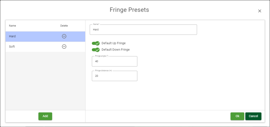
Click Add to create a new fringe preset, or select an existing field’s key from the list to change its settings. Configure the fields as follows:
Name Enter a unique name for the fringe preset.
Default Up Fringe Enabling this will cause this preset to be applied as the up fringe to new surfaces on import without having to be specified by the user. Default Down Fringe Enabling this will cause this preset to be applied as the down fringe to new surfaces on import without having to be specified by the user. Fringe angle Enter the preset fringe angle value. The fringe angle is the slope of the fringe given as the angle from horizontal. See Surface Model > Fringes for more information. Fringe distance Enter the preset fringe distance value. The fringe distance is the maximum horizontal distance from the boundary of the new surface to extend outwards. See Surface Model > Fringes for more information.
-
-
Select the files you want to upload. You can do this by making sure their checkboxes are selected in the file list. If you have many files, you can select all valid files by clicking the Select Valid button.
-
To remove files from the list of surfaces to import, select their checkboxes in the file list and the click the
 button.
-
-
Click Upload Files to upload the selected files.
After uploading, GeoSpatial Manager queues files in correct time order for processing into the combined surface. Switch to the ![]() Home page to view the surface.
Home page to view the surface.
