Surface Model
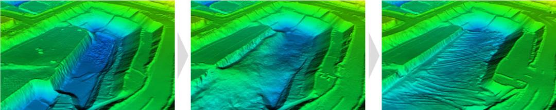
GeoSpatial Manager allows users to interact with a dynamic, integrated surface model representing their operation. This model encompasses both spatial and temporal information, being composed of multiple source surfaces that each represent part or all of the operation at specific points in time. These surfaces are merged into a combined model that represents the most up-to-date state of the operation for the selected time. Users can view the state of the operation at any point in time between the oldest and the most recent source surface, or compare the state between two points in time.
|
|
|
A combined surface displayed at three points in time. |
Merging new surfaces
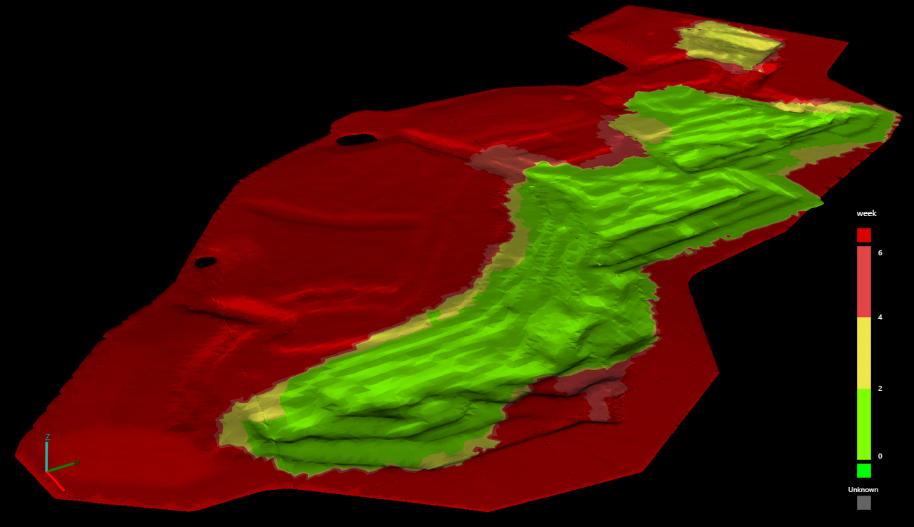
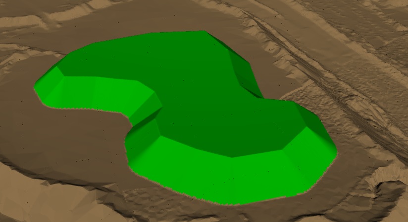
When new surfaces are imported, they are merged into the combined model. The combined model viewed at any given time typically includes data from multiple surfaces acquired at different times. Where these surfaces overlap, newer data always take precedence over older data. Colouring the surface by Time since capture is a useful way of visually identifying which parts of the model have been recently updated, as shown in the image below.
|
|
|
Surface coloured by time since capture. The most recently acquired data is coloured green. |
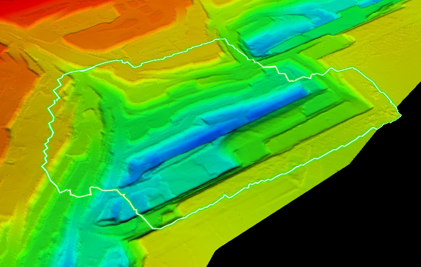
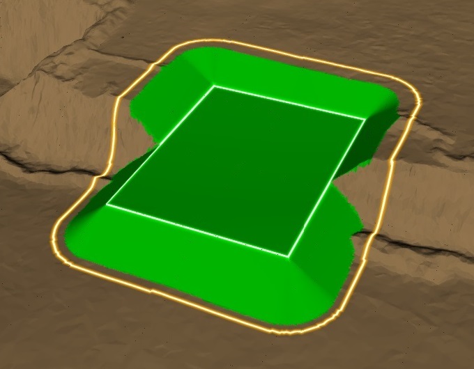
The source surfaces contributing to the combined model are individually preserved by GeoSpatial Manager after import and can be identified by a boundary highlight when a surface is moused over in the Surface Items list. To learn more about managing source surfaces and the operations that can be performed on them, see Managing Surface Items.
|
|
|
Boundary highlight showing the location of a source surface within the combined model. |
Time and positioning
The data stored in GeoSpatial Manager is the single source of truth for your operation. For this reason, it is essential that source surfaces imported into GeoSpatial Manager have been correctly modelled and positioned within the relevant coordinate system. Additionally, the acquisition date and time of each surface must be known and specified at import to ensure that surfaces appear in the correct chronological order.
If your surface filenames follow a systematic naming scheme incorporating the date and time, you can configure GeoSpatial Manager to automatically parse the date and time from the filename. Otherwise, you can set the date and time (or just the time component) manually.
For more information, see Importing Data and Site Settings > File Name Parsers.
Fringes
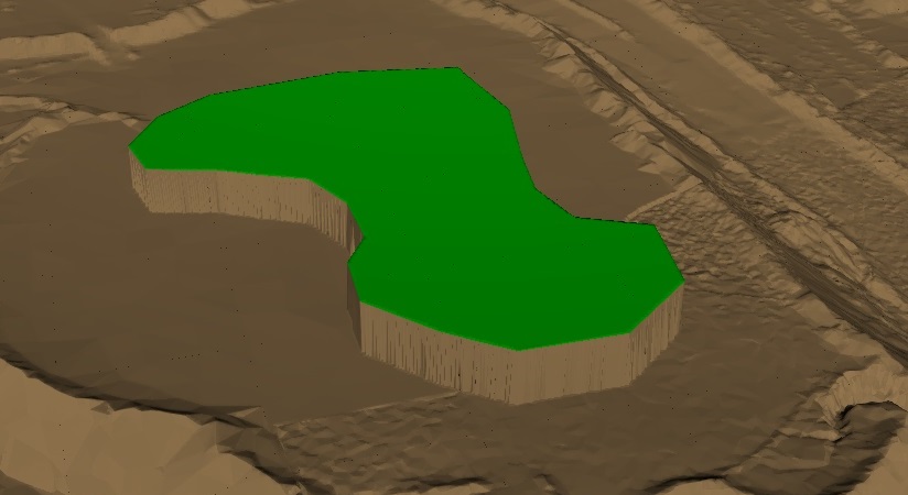
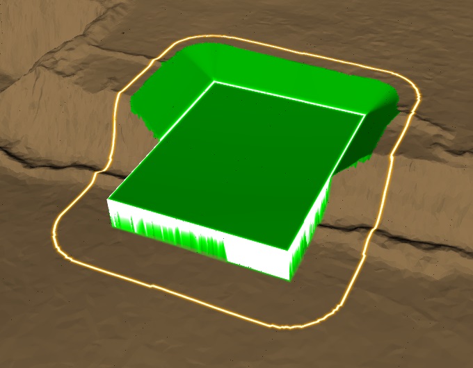
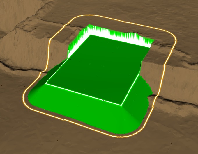
New surfaces can contain differences in elevation with the old surface along their boundary. These differences can result from minor registration discrepancies or missing data that was not captured in either the old or new surfaces. In such cases, GeoSpatial Manager can either honour the data exactly or alternatively add a fringe to the new surface. A fringe is a sloping extension added to the new surface to provide a smooth transition to the old surface. Without a fringe, elevation differences result in abrupt, cliff-like vertical jumps along the boundary.
|
|
|
A new surface (shown in green) with elevation differences handled in two ways. Left: With no fringe, the surface transitions with abrupt vertical jumps. Right: With a fringe, the surface transitions smoothly. |
|
Fringe angle and distance
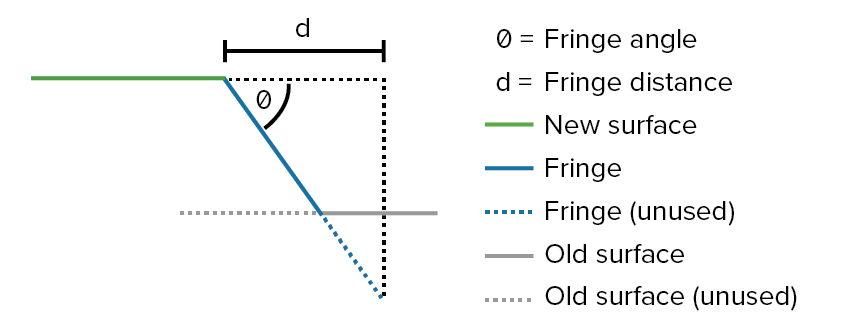
A fringe is defined by two parameters, as follows:
-
Angle: The slope of the fringe given as the angle from horizontal.
-
Distance: The maximum horizontal distance from the boundary of the new surface to extend outwards.
|
|
|
Profile view of a new surface with fringe showing the fringe angle and distance. |
Fringe direction
Fringes can be selectively added to new surfaces and customised according to their direction towards the old surface, as follows:
-
Up fringe: An up fringe slopes up from the new surface towards the old surface.
-
Down fringe: A down fringe slopes down from the new surface towards the old surface.
-
Both up and down: A fringe can have both up and down components, where some parts of the new surface are below the old surfaces, and some parts are above.
|
|
|
|
New surface with up fringe only (left), down fringe only (centre), and with both up and down fringes (right). The outer polygon indicates the fringe distance. |
||
Note: GeoSpatial Manager treats up and down fringes separately. That is, a fringe can have a different angle or distance parameter applied depending on whether it is an up or down fringe.
Applying fringes
Fringes can be specified when a surface is imported in the ![]() Fringes section of the
Fringes section of the ![]() Import tool. Alternatively, fringes can be added, modified, or deleted at any time after import in the surface details panel. See Managing Surface Items > Fringes for more information.
Import tool. Alternatively, fringes can be added, modified, or deleted at any time after import in the surface details panel. See Managing Surface Items > Fringes for more information.
Fringe presets can be configured to allow users to select predefined fringe parameters. See Importing Data > Fringes or Managing Surface Items > Fringes for more information.
