Product Description |
Maptek R3 Series MkII scanners are terrestrial laser scanners capable of capturing detailed and accurate 3D point clouds for surveying applications, including topographic and civil projects.
Scanner kit
Maptek R3 MkII laser scanner systems are supplied as a kit, inclusive of the selected scanner and accessories. Table 2-1 lists each scanner system with available configurations and options, along with their respective part numbers.
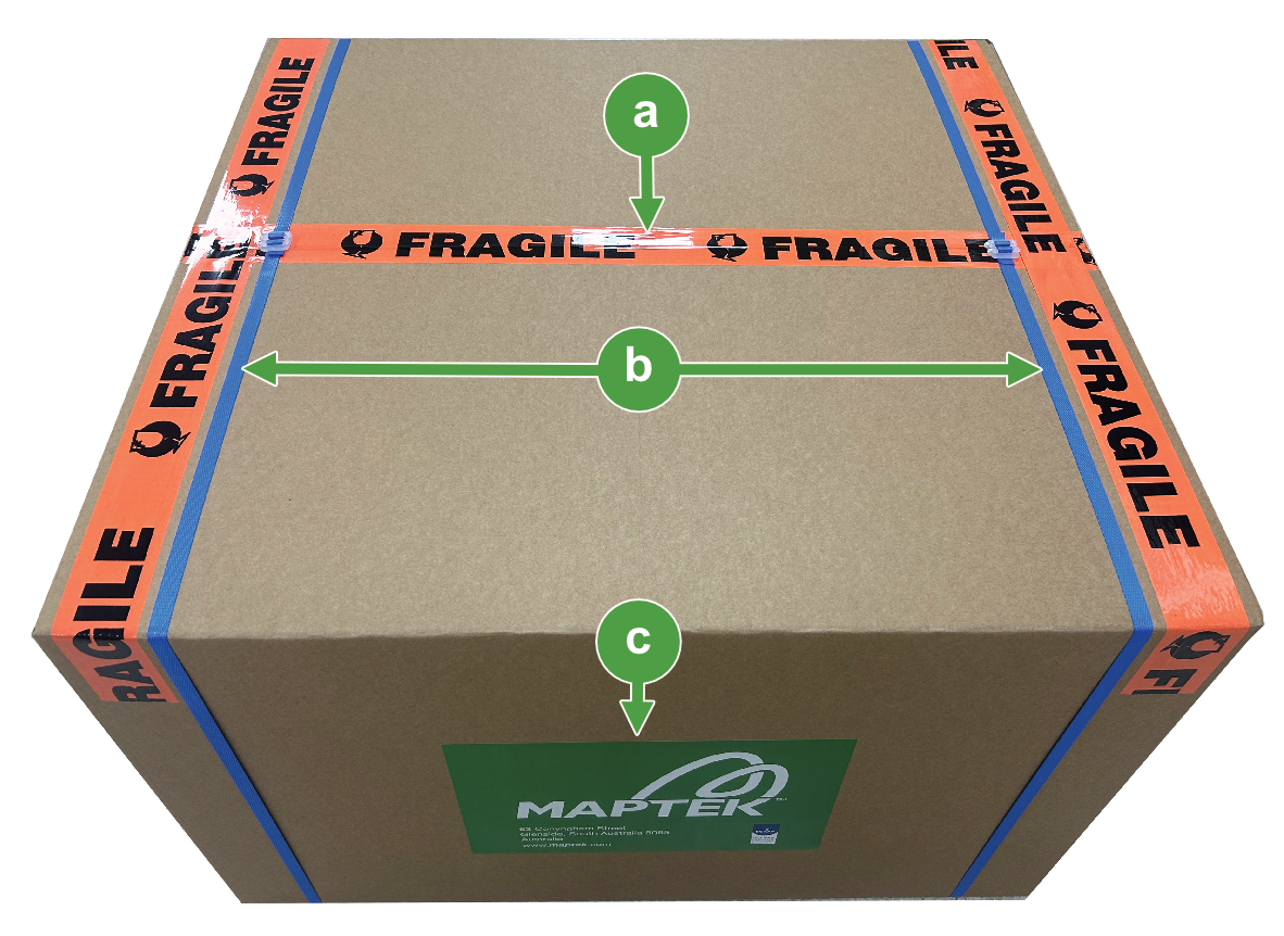
Unpacking the scanner kit
Referring to Figure 2-1, ensure the packing box is in the upright position before opening it. The top of the packing box has orange label tape marked “FRAGILE”. Also note the orientation of the Maptek product label on one side of the box.
To open the box, cut the straps and packing tape securing the lid.
|
|
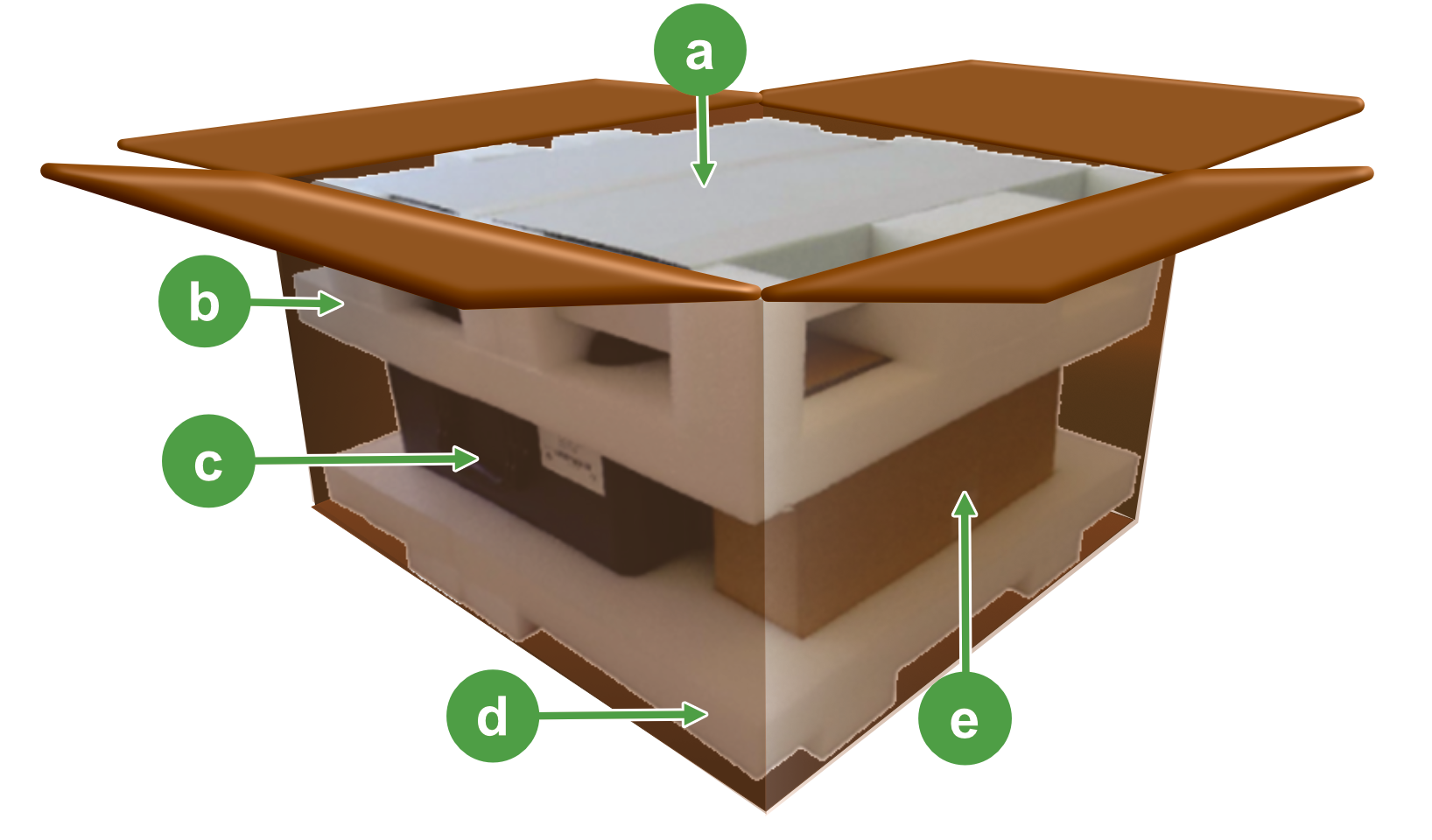
Figure 2-2 illustrates a typical scanner kit as shipped.
To unpack the scanner kit, follow these steps:
-
Remove the accessories box (if supplied).
-
Remove the upper foam cage.
-
Remove the backpack box (if supplied).
-
Remove the transit case.
Tip: Please retain the box and foam cages to use when returning the scanner for service or repair, if possible.
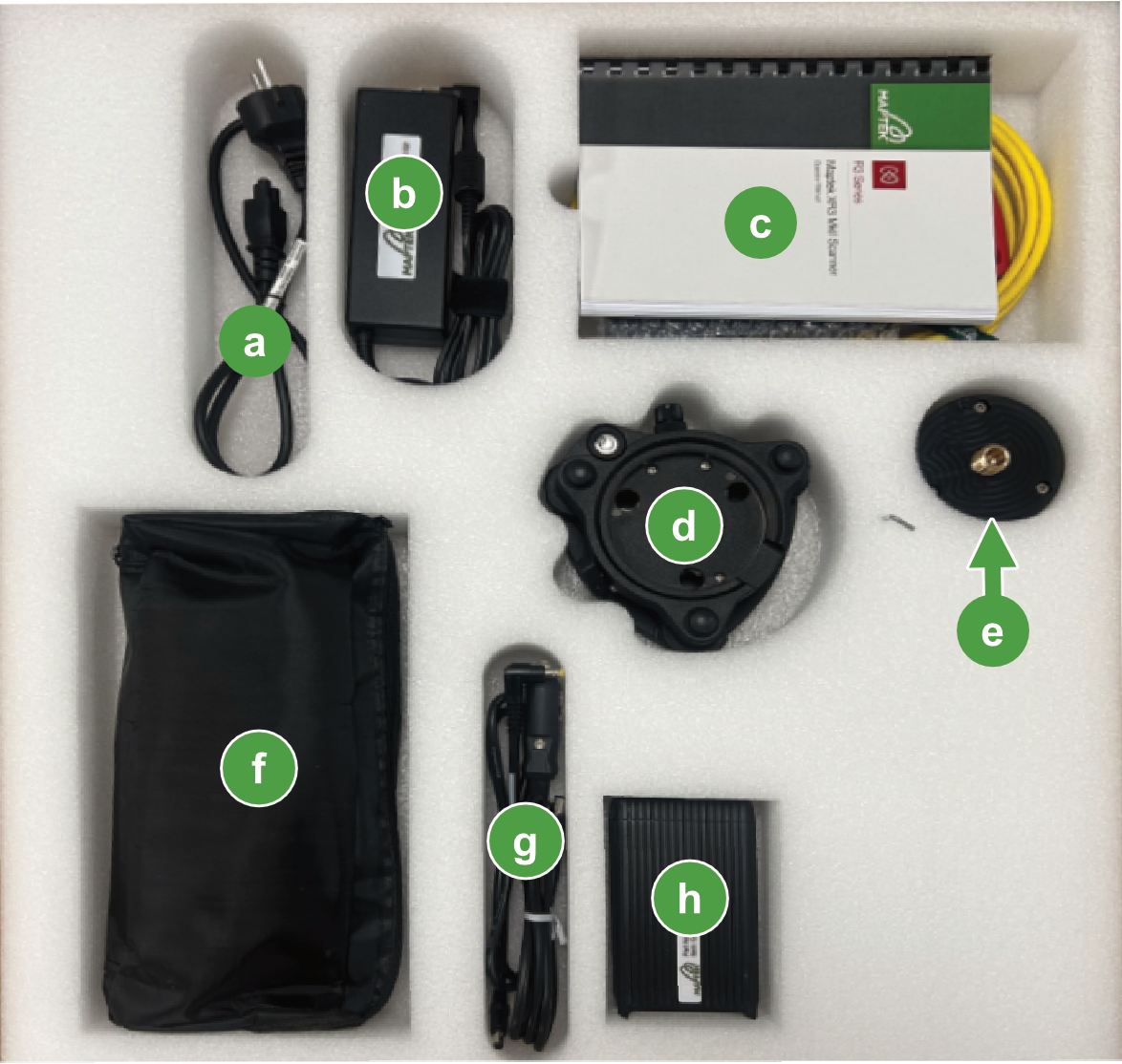
Accessories box contents (if supplied)
The accessories box contains items that are used with the scanner and the FieldHHC tablet. Figure 2-3 shows the items included.
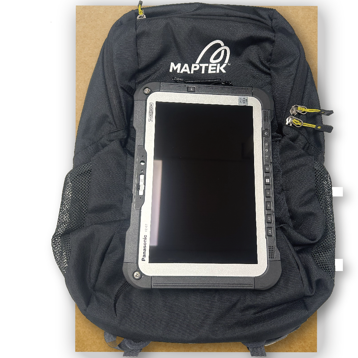
Backpack box items (if supplied)
The FieldHHC tablet and backpack are packaged in this box. You can also use the backpack to store any other accessories.
Note: Always store the FieldHHC tablet inside the padded section in the backpack to best protect its touchscreen. You can optionally store the tablet in the transit case.
|
|
|
Figure 2-4 Backpack box contents |
Transit case
Figure 2-5 illustrates transit case items as shipped. The FieldHHC tablet can subsequently be stored in the transit case if the foam insert ( ) is removed.
|
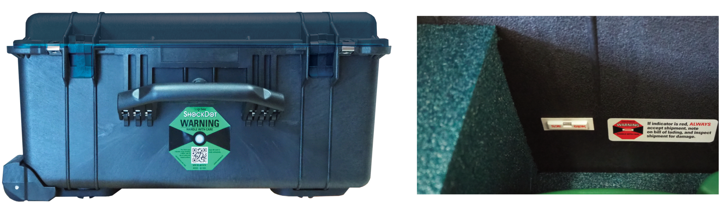
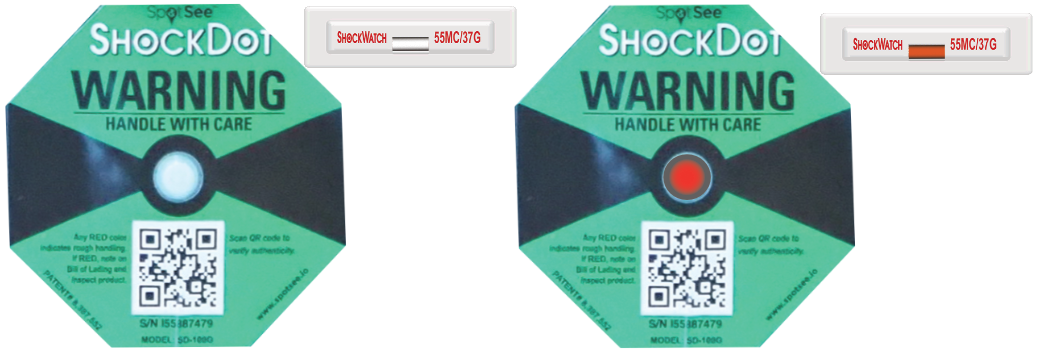
Shock indicators
Shock indicators detect possible rough handling by reacting to a predetermined amount of shock. They do not necessarily indicate damage. If damage is noted upon delivery, immediately contact the shipping company and Maptek for advice. There is an external and an internal shock indicator. Refer to Figure 2-6 for their locations. Figure 2-7 illustrates the contrast between undisturbed and triggered indicators.
Standard kit inclusions
Table 2-2 lists the items that are included in each scanner kit.
| Part | Kit | ||||||
|---|---|---|---|---|---|---|---|
| Name | Model | Part # | Qty | XR3 | SR3 | UR3 | Acc.1 |
| UR3 scanner | UR3 | 0990290 | 1 | ● | |||
| UR3 M20 | 0990291 | ||||||
| XR3 scanner | XR3-CT | 0990275 | 1 | ● | |||
| XR3-C | 0990276 | ||||||
| XR3-CT M20 | 0990278 | ||||||
| XR3-C M20 | 0990279 | ||||||
| XR3-D | 0990277 | ||||||
| XR3-CD | 0990282 | ||||||
| SR3 scanner | SR3-CL | 0990282 | 1 | ● | |||
| Tribrach adapter | 0102316 | 1 | ● | ● | ● | ||
| 6 mm T-shape hex key | 0102385 | 1 | ● | ● | ● | ||
| 3 m shielded Ethernet cable | 0160043 | 1 | ● | ● | ● | ||
| Transit case (XR3, SR3) | 0110083 | 1 | ● | ● | |||
| Transit case (UR3) | 0110210 | 1 | ● | ||||
| Optical tribrach | 0101000 | 1 | ● | ● | ● | ||
| Li-ion scanner battery | 0061014 | 2 | ● | ● | ● | ||
| Scanner battery charging kit | 0102275 | 1 | ● | ● | ● | ||
| FieldHHC tablet (Panasonic FZ-G2) | 0103038 | 1 | ● | ● | ● | ||
| 12 V car adapter for FieldHHC tablet | 0102271 | 1 | ● | ● | ● | ||
| 32 GB USB key | 0102067 | 1 | ● | ● | ● | ||
| 32 GB compact USB keys | 0102028 | 2 | ● | ● | ● | ||
| Backpack | 0102063 | 1 | ● | ● | ● | ||
| Operator manual | 0110140 | 1 | ● | ● | ● | ● | |
| GPS off-centre mount | 0081098 | 1 | ● | ||||
| Eyepiece cap | 0050472 | 1 | ●2 | ||||
| Neoprene jacket for XR3 M20 | 0102751 | 1 | ●3 | ||||
| Neoprene jacket for UR3 M20 | 0103105 | 1 | ●4 | ||||
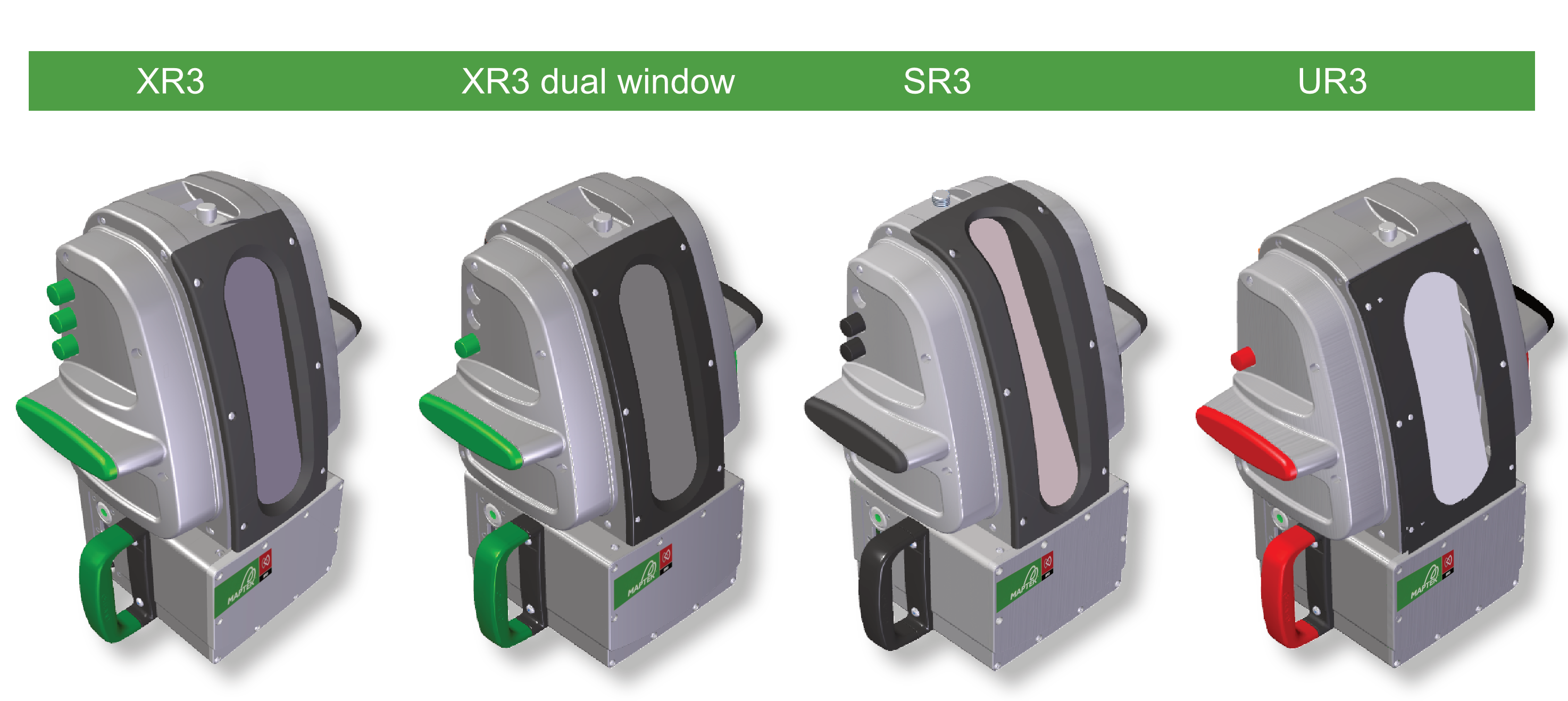
System components
The features and controls available on your scanner depend on the model. Figure 2-8 illustrates the models available in the R3 MkII range of scanners.
Scanner components
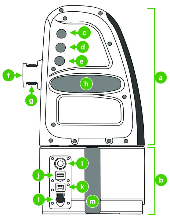
Figure 2-9 identifies the components of a scanner. Some components are model dependent.

|
The scanner head turns around its vertical axis (up to 360°) to allow data acquisition. |
|
|
The scanner body is the fixed part of the scanner. |

|
Telescope focus knob (XR3-CT only) Adjusts the focus of the objective lens when backsighting with the telescope. |

|
Elevation control knob (XR3-CT and SR3-CL only) XR3-CT: Adjusts the elevation of the telescope viewing field. |

|
Adjusts the azimuth position of the scanner head. |

|
Telescope eyepiece (XR3-CT only) Used to locate backsight targets. |

|
Telescope eyepiece dioptre focus bezel (XR3-CT only) Adjusts the eyepiece focus to your eye by focussing to the reticule inside the eyepiece. |

|
Allows the scanner to be placed horizontally on a flat surface. |

|
Scanner power button and status indicator For details, see Power button functions. |

|
Insert a USB key into this port to receive pushbutton and mobile device scans. |

|
Connect the FieldHHC tablet to this port using the supplied Ethernet cable when not using Wi-Fi, or when using the scanner with Sentry DMS or a mobile scanning platform such as Maptek Drive. |

|
Supplies power to the scanner (instead of using a battery) via the scanner power cable (part # 0102062) when used with Sentry DMS, Sentry FMS, and Maptek Drive. |

|
Use this handle when carrying the scanner in its upright position or when placing the scanner into its transit case, with the other hand holding the left side handle ( |

|
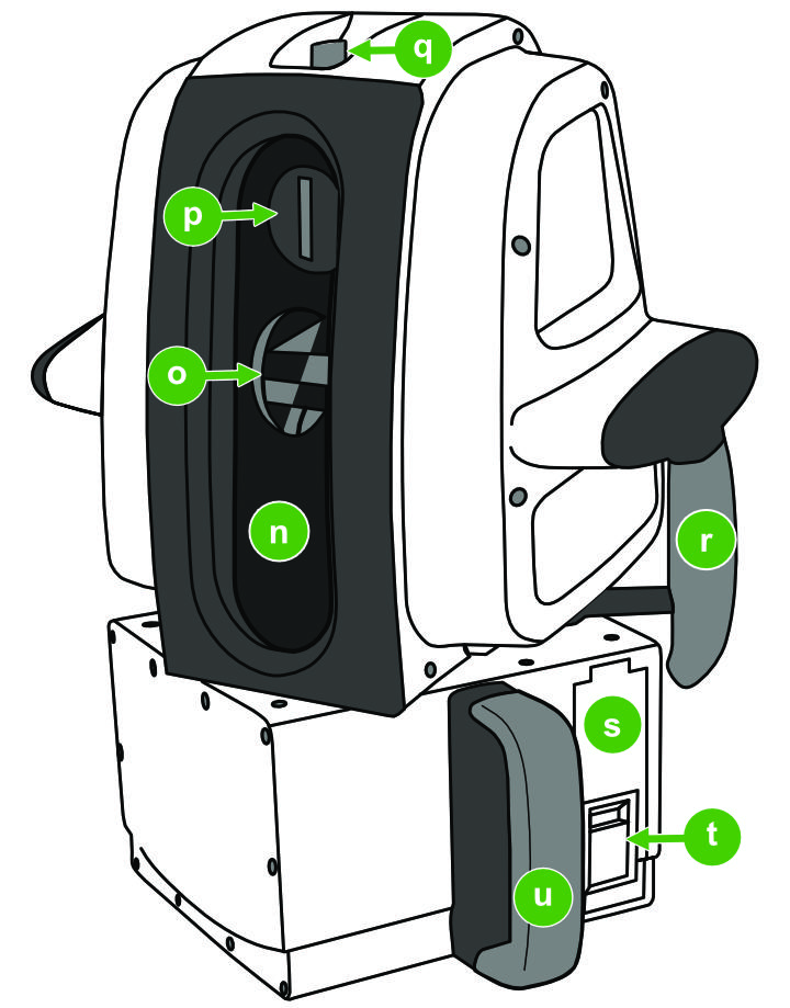
All optical data including lidar, camera, telescope image, and laser aimer beam, passes via this aperture. Scanning window configurations vary. To learn more, see Scanning window variants. |

|
The scanning mirror directs and receives laser pulses as it rotates, resulting in the collection of scan data as a series of vertically arranged points. |

|
Camera aperture (not applicable to XR3-D) The camera sensor allows photographic data to be associated with scan points. |

|
This mounting point allows you to fit GPS and radio devices to the scanner. |

|
Use this handle to carry the scanner with a single hand. |

|
Battery bay cover The scanner battery bay is accessed via this cover. |

|
Battery bay cover latch The latch secures and opens the battery bay cover. |

|
Use this handle when carrying the scanner in its upright position or when placing the scanner into its transit case, with the other hand holding the right side handle ( |
Scanner base
The scanner base includes mounting points for the tribrach adapter, stairwell adapter bracket, or vehicle mount (where supplied).
|
|
|
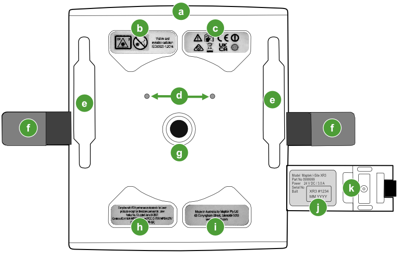
Figure 2-10 Scanner base features |
|
|
Front of scanner |
|
|
|
|
|
|
|
|
Tribrach adapter alignment sockets The sockets align with matching pins on the tribrach adapter to ensure correct orientation during installation. |
|
|
Double-ended key T-bolt key hole slots The slots fit a T-bolt at each end which secure the vehicle mount frame or stairwell bracket to the scanner base. |
|
|
These handles allow you to carry the scanner upright, or when packing or placing the scanner on a mount. |
|
|
The capture bolt on the tribrach adapter screws into this hole. |
|
|
This label displays laser performance compliance information. |
|
|
|
|
|
The serial number label is displayed inside the battery bay door. It also displays the scanner model, part number, and build date. |
|
|
Battery bay cover The battery bay cover is shown in the open position. |
Onboard scanner controls
Table 2-3 lists the controls that apply to specific scanner models.
| Scanner control | Scanner model | ||||
|---|---|---|---|---|---|
| UR3 | XR3-C | XR3-CT | XR3-D, XR3-CD |
SR3 | |
| Power button | ● | ● | ● | ● | ● |
| Azimuth control knob | ● | ● | ● | ● | ● |
| Elevation control knob | ● | ● | |||
| Telescope focus knob | ● | ||||
| Telescope dioptre bezel | ● | ||||
Power button functions
The power button performs several different functions, as follows:
|
Power the scanner on or off |
Press the power button to turn the scanner on or off. |
|
A pushbutton scan only requires a scanner with no external controller. To learn more, see Scanning to USB. |
|
| Enable and disable Wi-Fi |
Wi-Fi is enabled by default. In cases where Wi-Fi is not a practicable option, it can be disabled. To learn more, see Enabling or disabling Wi-Fi on the scanner. |
Status indicator light
The power button displays sequences of green and red lights to indicate various states and operations. The meaning of each light sequence is explained in Table 2-4.
| When | Light sequence | Meaning |
|---|---|---|
|
Inserting a battery |
|
Battery has a good charge. |
|
|
Battery is spent. | |
|
Starting the scanner |
|
Scanner starting with Wi-Fi enabled. |
|
|
Scanner starting with Wi-Fi disabled. | |
|
Scanner is powered |
|
Scanner is idle. |
|
Taking a preview |
|
The scanner is acquiring a preview. |
|
Taking a scan |
|
The scanner head is moving to the start of scan position. |
|
|
Scanning is in progress. |


Control knob functions
The control knobs have variable sensitivity based on how quickly you turn them. To reach your target location faster, turn the knob quickly. For precise adjustments, turn the knob slowly.
| Action | Effect | ||
|---|---|---|---|
| Focus knob | Elevation knob | Azimuth knob | |

Slow turn |
Precisely adjust the telescope focus. | Precisely adjust elevation. | Precisely adjust azimuth. |

Fast turn |
Roughly adjust telescope focus. | Roughly adjust elevation. | Traverse scanner head in larger increments. |

Fast flicking motion |
Rotate scanner head continuously. | ||
Tip: Spin the azimuth knob with a fast flicking motion in the intended direction of rotation to traverse the head continuously. To cancel its rotation, turn the azimuth knob in the opposite direction.
Note: The scanner head automatically stops traversing when it reaches either end of its rotation extent.
Note: The scanner head automatically returns to its home (forward-facing) position when turning off the scanner.
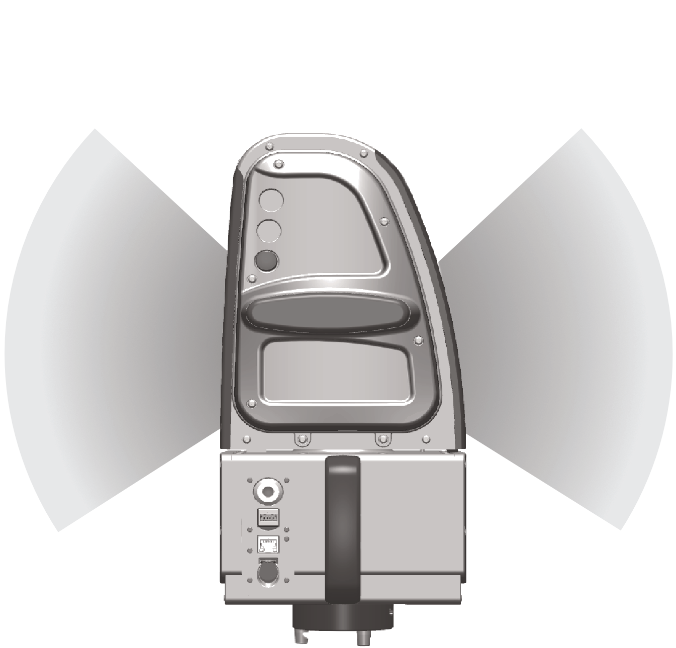
Scanning window variants
Table 2-6 explains the scanning window configuration used by each scanner model.
| Scanner model | Window configuration | Description |
|---|---|---|
|
|
Standard window with model-specific scanning elevation extents. | |
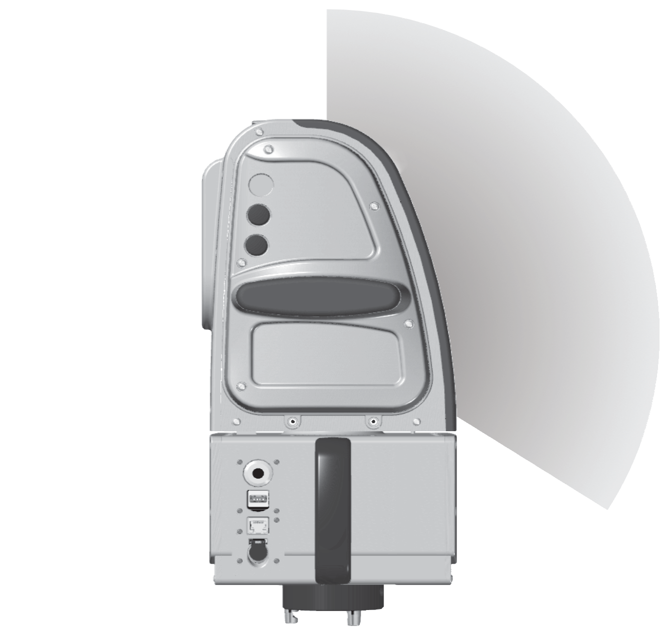
| XR3-CD XR3-D |
|
Dual front- and rear-facing scanning windows. The maximum elevation extent is model-specific. |
| SR3 |
|
Single window permits scanning up to +90° from the scanner’s level plane. |
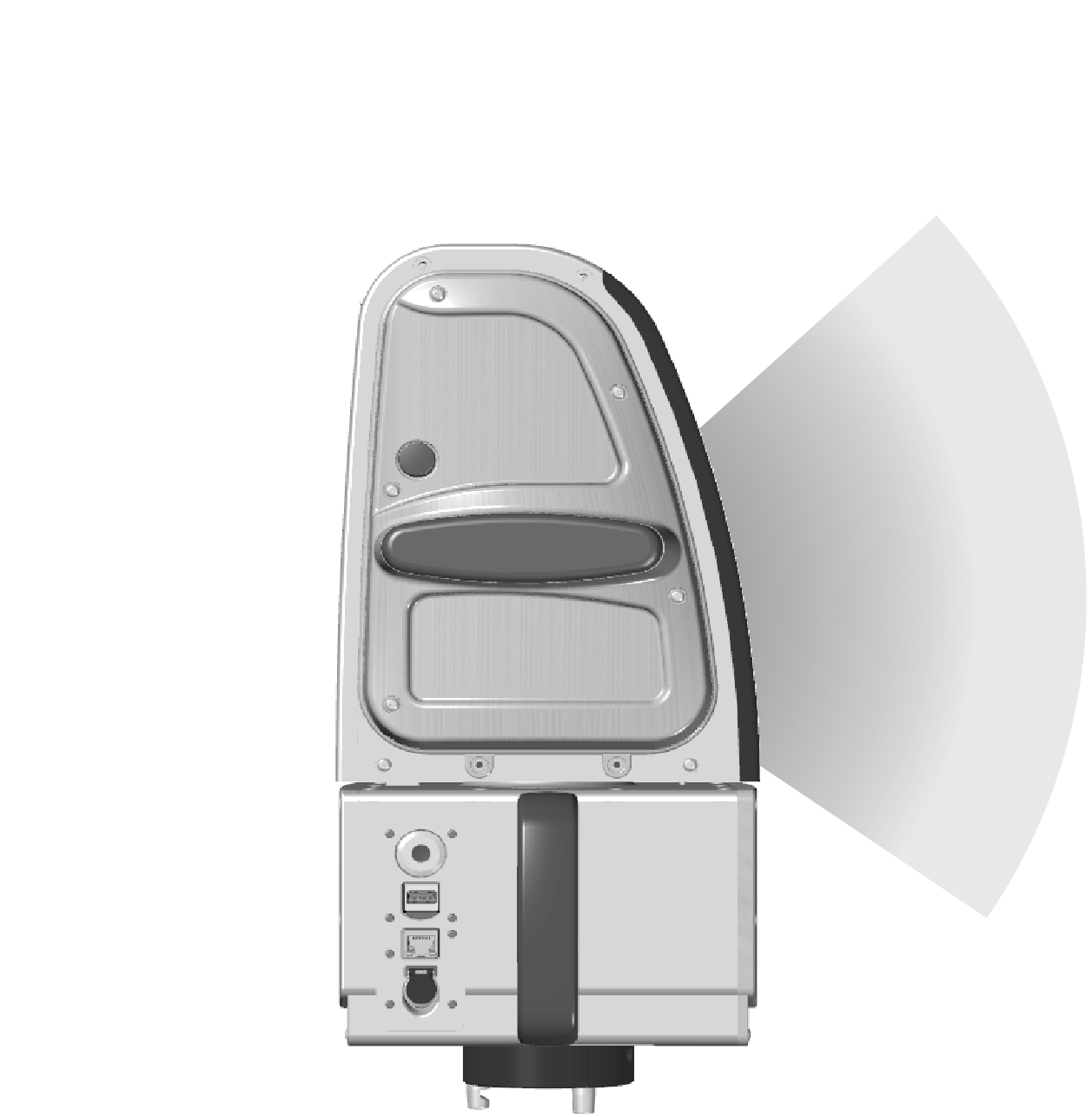
Consult Specifications > Table B-2 for the scanning elevation extents of your scanner model.
FieldHHC tablet
The FieldHHC tablet uses a touchscreen interface for performing all scanning tasks, including the following:
-
Taking scans
-
Configuring the tablet and the scanner
-
Importing, exporting, viewing, and managing data
-
Performing various scan post-processing tasks
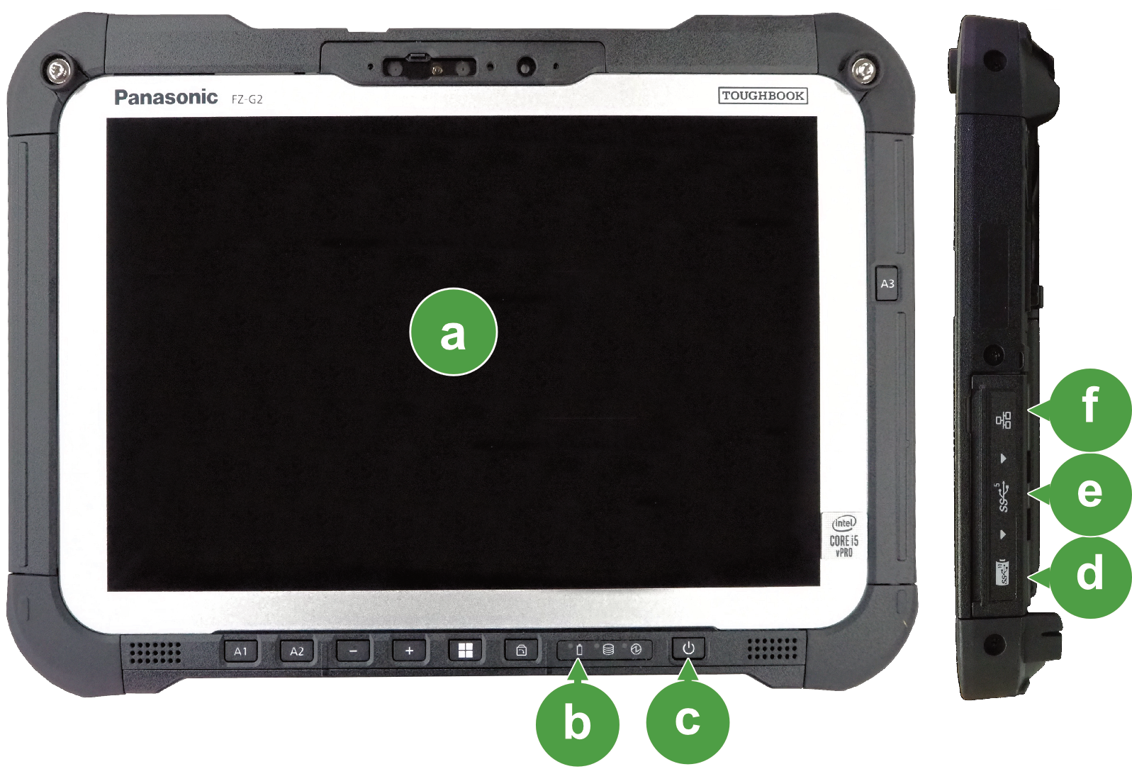
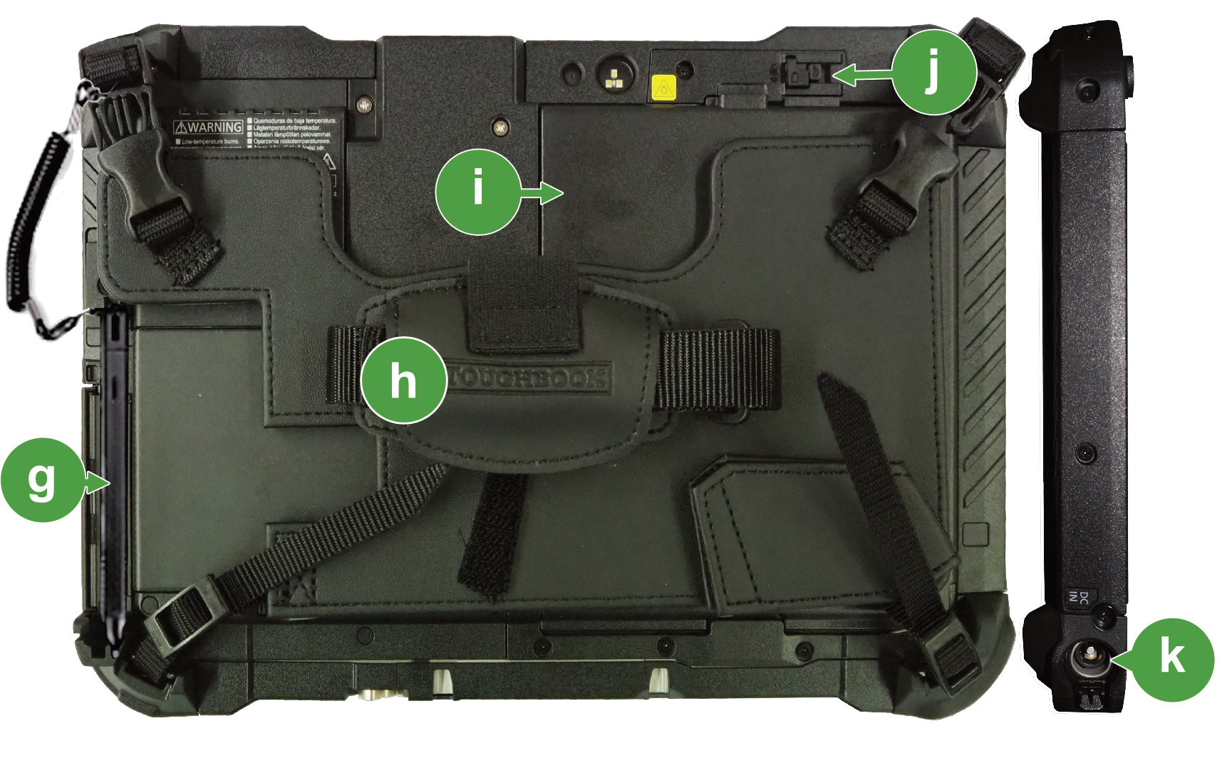
Figure 2-11 illustrates the main components used on the FieldHHC tablet.
|
|
|
|
Touchscreen |
|
Stylus |
|
|
Battery state indicator |
|
Hand grip |
|
|
Power ON-OFF button |
|
Tablet battery |
|
|
USB-C port |
|
Battery latch |
|
|
USB-A port |
|
DC-in socket |
|
|
LAN port |
Note: The tablet is supplied with the manufacturer’s user manual.
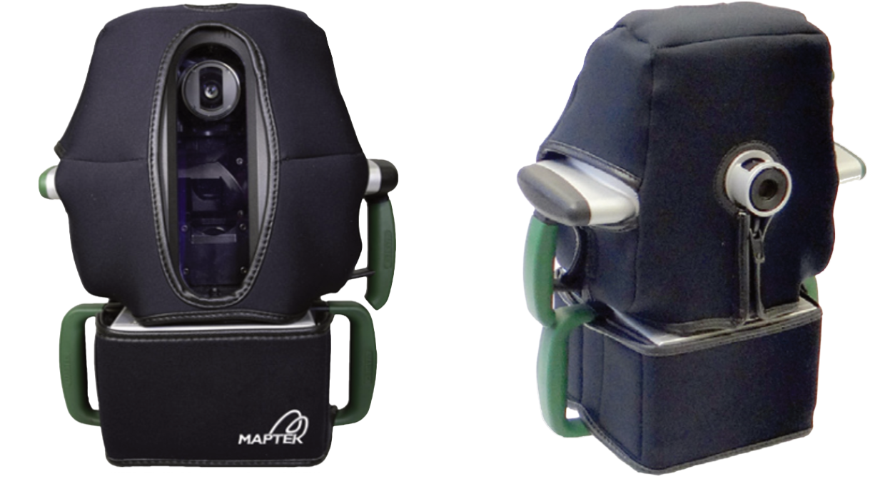
Cold climate option (XR3 M20 and UR3 M20)
XR3 and UR3 scanners fitted with the cold climate option allow continuous operation in cold climate conditions. Cold climate scanners use an integrated active heating system and a removable neoprene jacket to maintain the system operating temperature.
To learn more, see Scanning in cold conditions.
|
|
|
Figure 2-12 Views of an XR3-CT M20 scanner with its neoprene jacket. |