Filters
Source file: filters-drop-down.htm
The Filters drop-down hosts a number of different filter tools that are useful for specific situations.
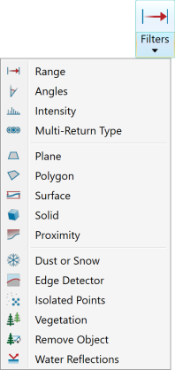
Expand below for details on each filter tool.
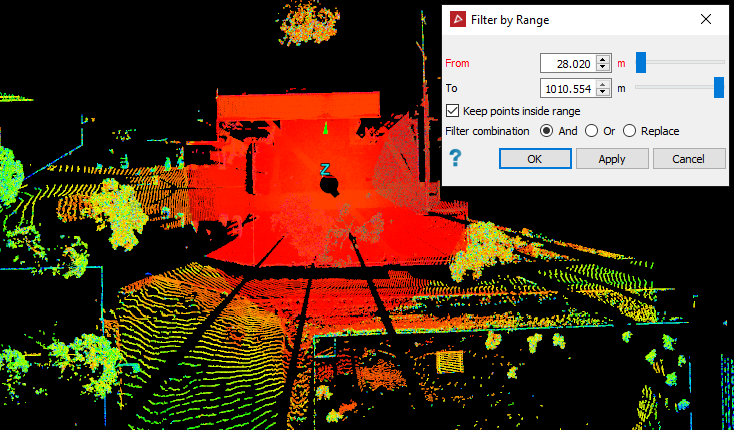
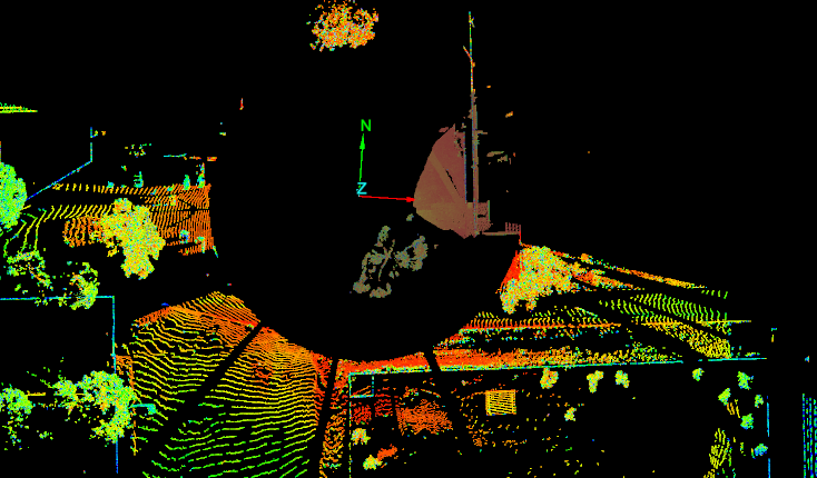
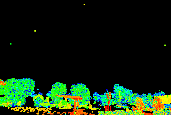
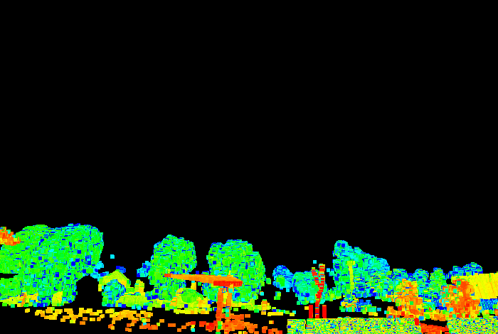
The Range filter retains or removes points inside or outside a specified range from the scanner. This tool is typically used to filter out points closest to the scanner, which are not always required, such as with scans taken from a pit floor.
-
To filter by range, follow these steps:
-
Select the scans

 to be filtered.
 -
On the Position and Filter tab, in the Filter group, select
 Range from the Filters drop-down list.
-
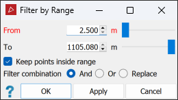
Specify the range limits as From and To distances.
-
Select or clear Keep points inside range, depending on which points you want to retain.
-
Select the required Filter combination (see Filter Combinations).
-
Click OK or Apply.
-
|
|
|
|
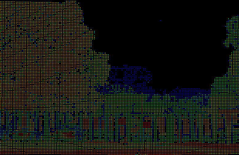
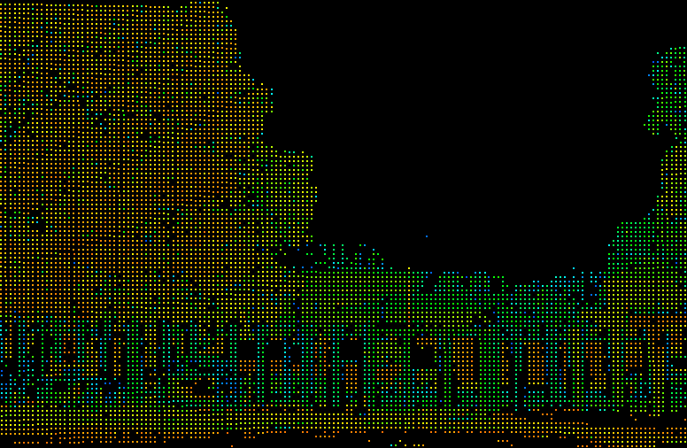
Before (left) and after (right) filtering by range. All points in the range |
|
Tip: You can redisplay filtered points
by clicking ![]() Show All. See Show All.
Show All. See Show All.
The Angles filter retains or removes scan points by vertical and horizontal angular extents.
-
To filter by angles, follow these steps:
-
Select the scans

 to be filtered.
 -
On the Position and Filter tab, in the Filter group, select
 Angles from the Filters drop-down list.
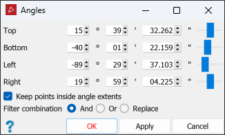
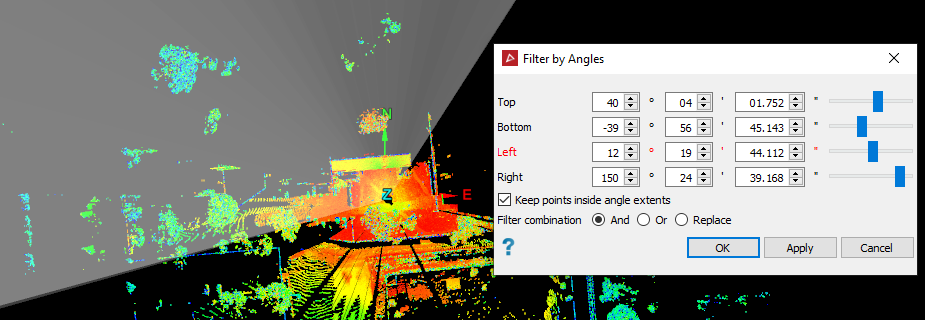
Note: When a single scan is selected, its angular extents are displayed in the angle fields. These angles are relative to the scanner’s pointing direction (azimuth and elevation = 0°).
-
Enter the vertical angle extents in the Top and Bottom fields.
-
Enter the Left and Right fields. These are the horizontal extents.
Note: Negative angles indicate directions below or to the left of the scanner’s pointing direction.
-
Select or clear Keep points inside angle extents, depending on the points you want to retain.
-
Select the required Filter combination (see Filter Combinations).
-
Click OK or Apply.
-
|
|
|
Preparing to filter by angles. Planes displayed on-screen indicate the filtering angles. |
|
|
|
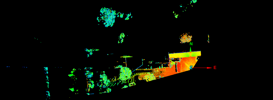
Result of filtering by angles. |
Tip: You can redisplay filtered points
by clicking ![]() Show All. See Show All.
Show All. See Show All.
The Intensity filter removes scan points based on intensity of the returned laser signal. This is useful for filtering dust clouds, which typically have low intensity, or for locating survey reflectors, which return high intensities.
-
To filter by intensity, follow these steps:
-
Select the scans

 to be filtered.
 -
On the Position and Filter tab, in the Filter group, select
 Intensity from the Filters drop-down list.
-
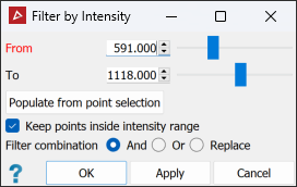
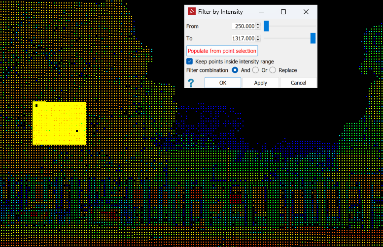
Enter an intensity range in the From and To fields. Alternatively, select an area representing the intensity filter range in the view window, then click Populate from point selection to populate intensity range values.
-
Select whether to keep values inside or outside this range. In the example above, points from 591 to 1118 intensity values will be kept, and anything else filtered out.
-
Select the required Filter combination (see Filter Combinations).
-
Click OK or Apply.
-
|
|
|
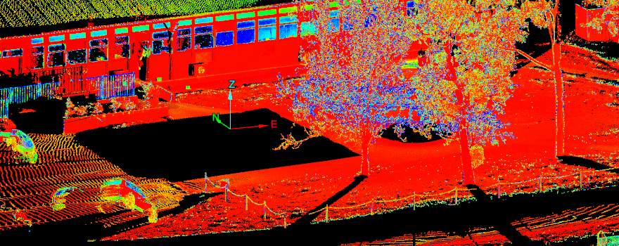
A low intensity dust cloud (blue coloured particles) unfiltered. |
|
|
|
The low intensity dust cloud filtered out. |
Tip: You can redisplay filtered points
by clicking ![]() Show All. See Show All.
Show All. See Show All.
Scanner lasers can partially reflect off objects such as vegetation, dust, droplets and insects, then continue to other obstacles in their paths, resulting in multiple points along a scan line. The Multi-Return Type filter removes unwanted multi-return points.
-
To filter multi-return points:
-
Select the scans

 to be filtered.
 -
On the Position and Filter tab, in the Filter group, select
 Multi-Return Type from the Filters drop-down list.
 -
Select the required Return type from the following:
- All: All scan points collected.
- First: The first (nearest) obstacle detected.
- Last: The last (farthest) obstacle detected.
- Best: The strongest signal returned from an obstacle.

With this filter you can switch between the different types of scan points according to their scan return type, provided this scan data exists.
- Click OK or Apply.
-
Tip: You can redisplay filtered points
by clicking ![]() Show All. See Show All.
Show All. See Show All.
The Plane filter removes points on one side of a plane in 3D space. This is useful for removing points above or below specific elevations, or for removing ceiling points for better visualisation of indoor scenes.
-
To filter by plane, follow these steps:
-
On the Position and Filter tab, in the Filter group, select
 Plane from the Filters drop-down list.
-
Choose how to define the plane from the Plane drop-down list options. (The default option is Axis aligned).
Important: Before selecting points to define the plane, click in one of the coordinate fields. Otherwise, the point selection will determine the scan to be filtered.

Three points
Define the plane by specifying three points.

Point and normal
Define the plane by specifying one point and defining its normal direction.

Point and orientation
Define the plane by specifying one point and orienting the plane so the current view is its normal.

Facet and offset
Pick a triangle to define the plane's orientation, and then specify how far above or below that facet the plane should be.

Point, strike and dip
Define the plane by specifying a point and then providing dip/strike angles to specify the orientation of the plane through that point.

Axis aligned
Define the plane by selecting an axis pair then picking a point to define the offset along the third axis.

Action plane
Use the action plane of the current view.
-
Select the scans

 to be filtered.
 -
Select Keep points above plane to retain the points above the defined plane. If not selected, the points above the plane will be filtered out and points below will be retained.
-
Select the required Filter combination (see Filter Combinations).
-
Click OK or Apply.

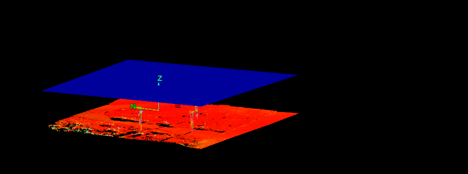
The filter plane will be displayed, indicating where the points will be filtered out.
-
|
|
|
The above scan filtered by plane, keeping points above the plane. |
Tip: You can redisplay filtered points
by clicking ![]() Show All. See Show All.
Show All. See Show All.
The Polygon filter removes scan data either inside or outside a user-defined polygon.
-
To filter by polygon, follow these steps:
-
Create or select a polygon to use (see 2D Polygon and Polygon). Alternatively, you can create a polygon region from within the polygon filter tool at step 3.
-
On the Position and Filter tab, in the Filter group, select
 Polygon from the Filters drop-down list.
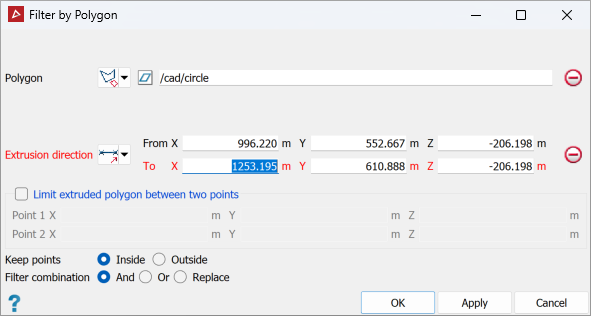
- Drag the polygon from step 1 into the Polygon field if it has already been created. Otherwise, create a polygon region from within the polygon filter tool using By points.
-
Set the Extrusion direction according
to the following options:

Two points
Define the direction by specifying two points.

Facet
Make the direction perpendicular to a selected facet.

Axis aligned
Define the direction by an axis of the view window.

Bearing and inclination
Define the direction by a bearing and inclination angles.

Action plane axis
Define the direction by an axis of the action plane.

Polygon best-fit plane normal
Define the direction as the normal to a plane-of-best-fit to a polygon.
-
Select Limit extruded polygon between two points and enter the limit point coordinates to limit the height and depth of the filter.
Important: Before selecting points to define the extrusion direction and limits, click in the relevant coordinate fields. Otherwise, the point selection will determine the scans to be filtered.
The projected polygon boundary will be displayed in grey.
-
Select the scans

 to be filtered.
 -
For Keep points, select either Inside or Outside according to which points you wish to retain.
-
Select the required Filter combination (see Filter Combinations).
-
Click OK or Apply.
-
|
|
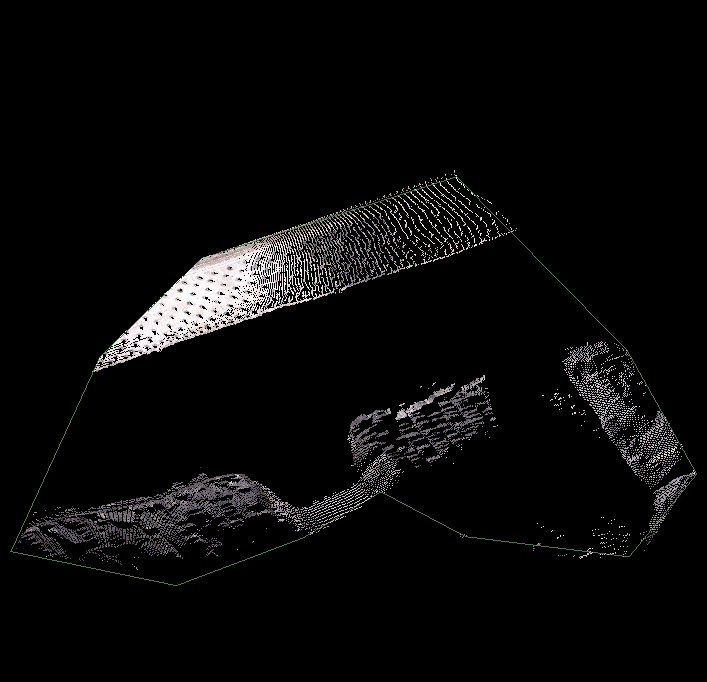
|
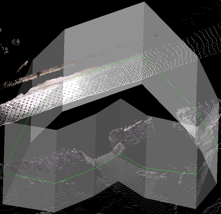
Data to be filtered selected, polygon region defined. |
|
|
|
Keep data inside the polygon chosen. |
|
|
|
Final filtered data. |
Tip: You can redisplay filtered points
by clicking ![]() Show All. See Show All.
Show All. See Show All.
The Surface filter removes scan points on one side of a surface. This is useful for removing points above or below specific elevations, or for removing ceiling points for better visualisation of indoor scenes.
-
To filter by surface, follow these steps:
-
On the Position and Filter tab, in the Filter group, select
 Surface from the Filters drop-down list.
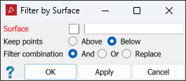
-
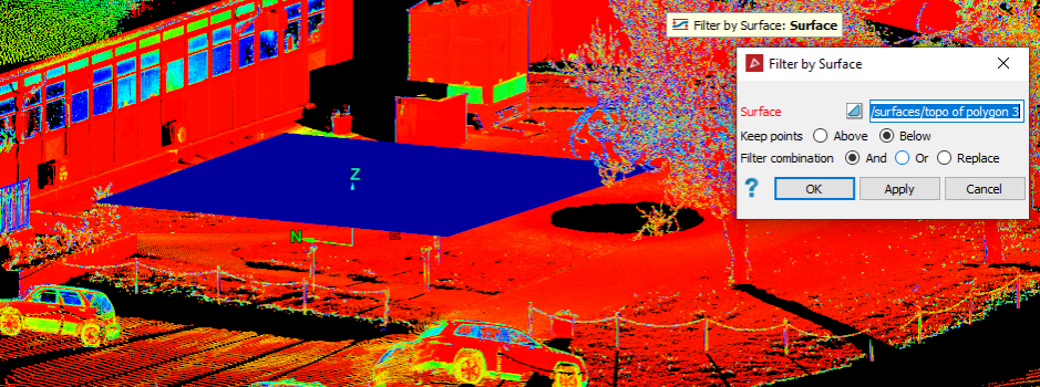
Drag the surface

 to use in the filter into the Surface field.
-
Select the scans

 to be filtered.
 -
For Keep points, select either Above or Below according to which points you wish to retain.
-
Select the required Filter combination (see Filter Combinations).
-
Click OK or Apply.
-
|
|
|
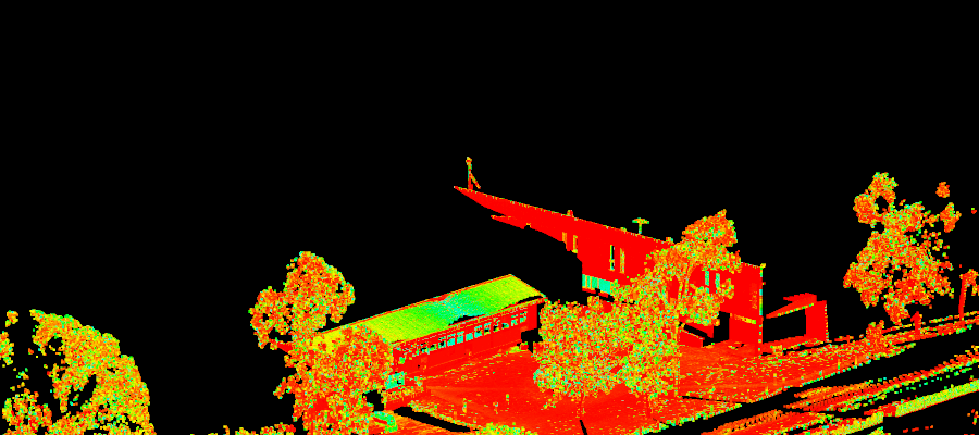
Result of keeping the points Below the surface. |
Tip: You can redisplay filtered points
by clicking ![]() Show All. See Show All.
Show All. See Show All.
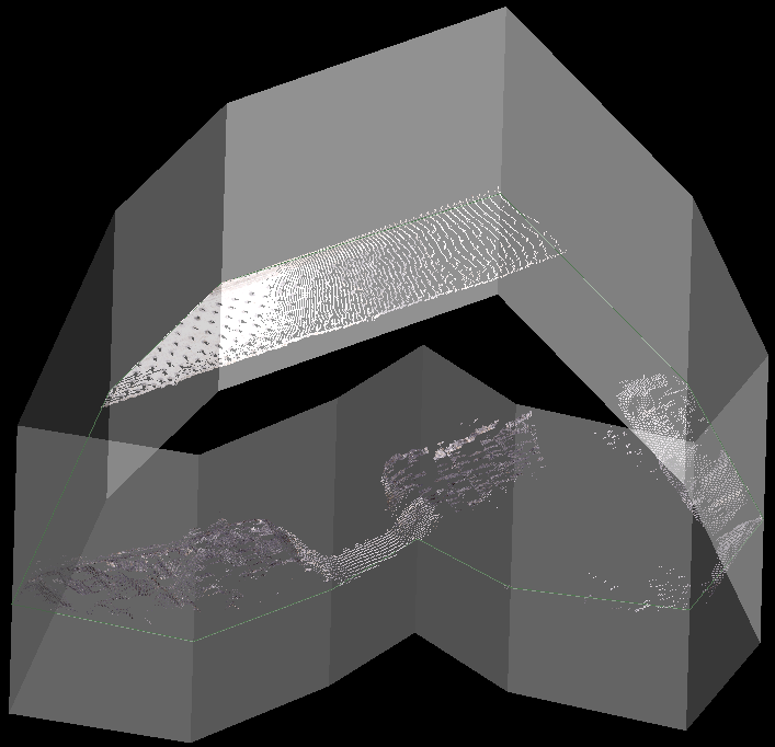
The Solid filter removes scan points inside or outside a 3D solid shape.
This is an extension of the filter-by-polygon tool (see Polygon). While the filter-by-polygon tool can define a region based on a polygon extruded into 3D space, the filter-by-solid tool allows full control in defining the 3D volume of interest. For example, this allows a more detailed control in defining regions around caverns in underground mines. It is also useful for filtering contents of storage bunkers and bays.
-
To filter by solid:
-
Create or select a 3D solid shape
 to use.
 -
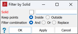
On the Position and Filter tab, in the Filter group select
 Surface from the Filters drop-down list select
  Solid.
-
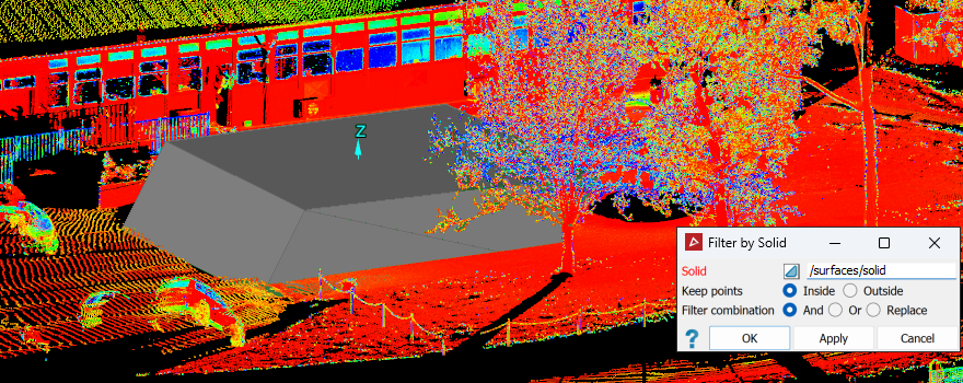
Drag the solid shape into the Solid field. The solid shape boundary is displayed in grey.
-
Choose to keep points Inside or Outside the solid shape.
-
Select the required Filter combination (see Filter Combinations).
-
Select the scans

 to filter.
 -
Click OK or Apply.
-
|
|
|
Result of keeping the points outside of the solid. |
Tip: You can redisplay filtered points
by clicking ![]() Show All. See Show All.
Show All. See Show All.
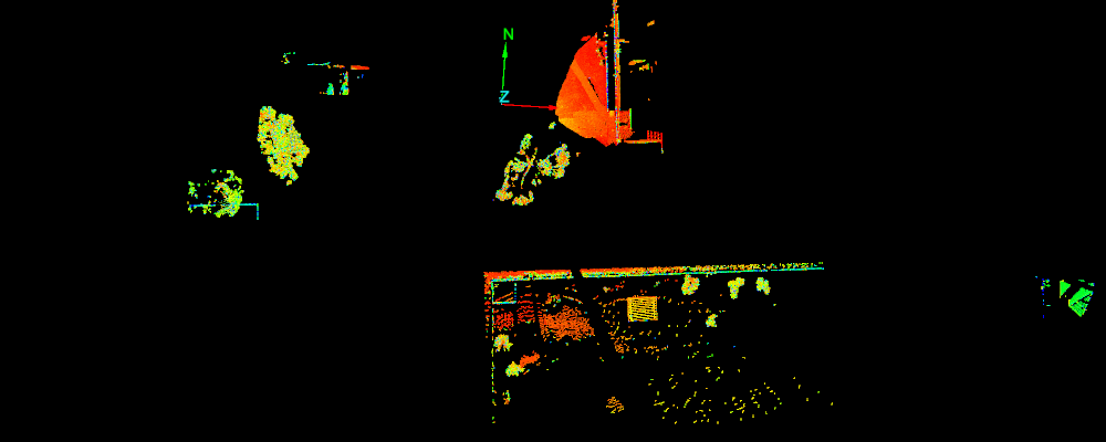
The Proximity filter retains or removes points according to their distance from an object, and is useful for scans whose filtered points have been restored after having been filtered to create a model. Run the proximity filter to re-filter the data, to retain points close to the modelled object.
-
Follow these steps to filter by proximity:
-
On the Position and Filter tab, in the Filter group, select
 Proximity from the Filters drop-down list.
-
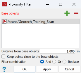
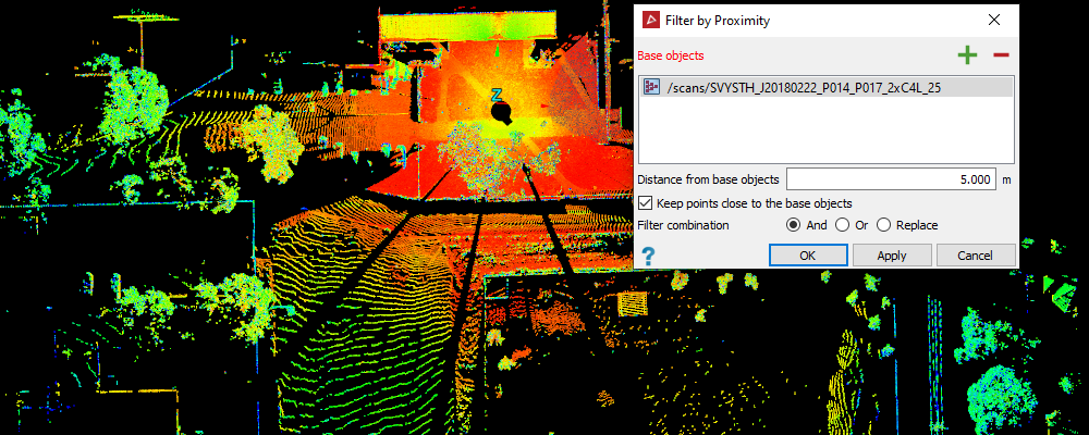
Add one or more reference objects to the Base object field either by dragging, or selecting and clicking
 .
. -
Enter the Distance from base object for points to be kept or removed.
-
Select Keep points close to the object to keep the points within the defined distance.
-
Select the required Filter combination (see Filter Combinations).
-
Select the scan

 or points to be filtered.
-
Click OK or Apply .
-
Tip: You can redisplay filtered points
by clicking ![]() Show All. See Show All.
Show All. See Show All.
The Dust or Snow filter removes small unwanted points, usually of dust or snow particles.
-
To filter dust or snow particles, follow these steps:
-
Select the scans

 to be filtered.
Tip: While this filter will work with several scans simultaneously, it will be easier to work with them individually if they have different origins.
-
On the Position and Filter tab, in the Filter group, select
 Dust or Snow from the Filters drop-down list.
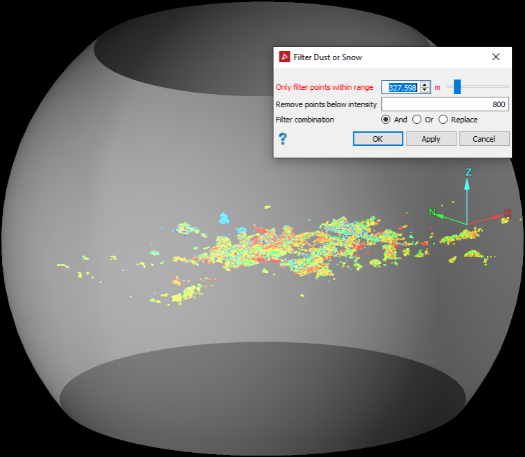
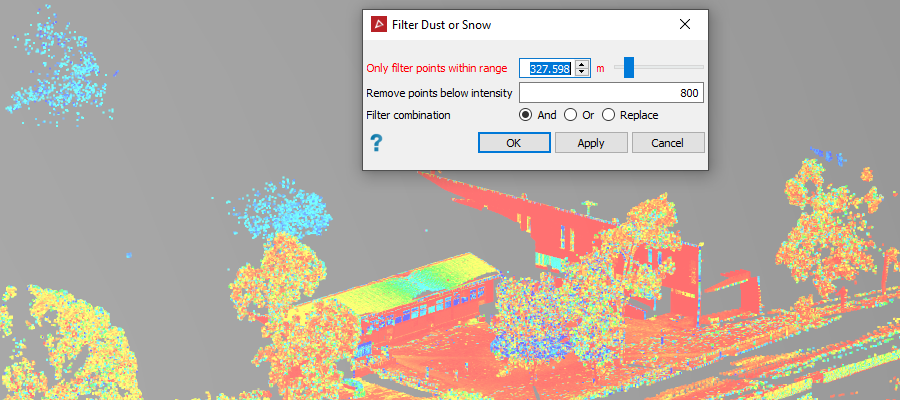
The panel will open and the active view window will display translucent spheres representing the data range around the scans’ origins.
-
Enter a value for the Only filter points within range setting by entering a value or using the slider. The range setting defines the maximum distance of points to filter from a scan’s origin. The sphere sizes will change with the range setting.
-
Enter the intensity value below which you want to filter out points in the Remove points below intensity field. Dust and snow particles are typically represented by low intensity scan points.
Tip: To get an idea of an intensity value, click on a low intensity scan point, then press Ctrl+I+I to have the point statistics displayed in the report window.
-
Select the required Filter combination (see Filter Combinations).
-
Click OK or Apply.
-
|
|
|
Result of filtering out intensities below |
Tip: You can redisplay filtered points
by clicking ![]() Show All. See Show All.
Show All. See Show All.
The Edge Detector filter detects and retains points along edges in a scan, such as toes and crests in a pit.
-
To detect edges, follow these steps:
-
Select the scans

 to be filtered.
 -
On the Position and Filter tab, in the Filter group, select
 Edge Detector from the Filters drop-down list.
-
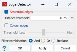
Select Structural edges or Colour edges and set their thresholds, as described below:
-
Structural edges are groups of points that define the edges of planes, such as walls of buildings, or flat surfaces such as joint planes of rock faces. Distance threshold is a measurement used to identify edges. Points closer to a local plane than the distance threshold are removed. The smaller the distance threshold, the more points will be retained. Increase the distance threshold to reduce the number of smaller edges and retain only the more clearly defined edges.
Tip: If results are unsatisfactory, try smoothing the points before detecting structural edges. See Smooth Scan.
-
Colour edges are groups of points that define areas of different colours, such as painted walls or geological boundaries. To apply the Threshold for colour edges, drag the slider. Low to retain most of the data and High to remove most of the data, leaving only the sharpest colour edges.
Note: If both the structural and colour options are applied, the filter will use both to produce the result.
-
-
Select the required Filter combination (see Filter Combinations).
-

Tip: You can redisplay filtered points
by clicking ![]() Show All. See Show All.
Show All. See Show All.
The Isolated Points filter removes points that are further than a user-defined distance from any other points. This
can be useful for filtering dust particles or insects that have been
scanned, but have been missed by the Intensity
-
To filter isolated points:
-
Select the scans

 to be filtered.
 -
On the Position and Filter tab, in the Filter group, select
 Isolated Points from the Filters drop-down list.
-
Enter a suitable Point separation. Points further than this distance from any neighbouring points will be filtered.
-
Select the required Filter combination (see Filter Combinations).
-
Click OK or Apply
-
|
|
|
|
Before (left) and after (right) filtering isolated points. |
|
Tip: You can redisplay filtered points
by clicking ![]() Show All. See Show All.
Show All. See Show All.
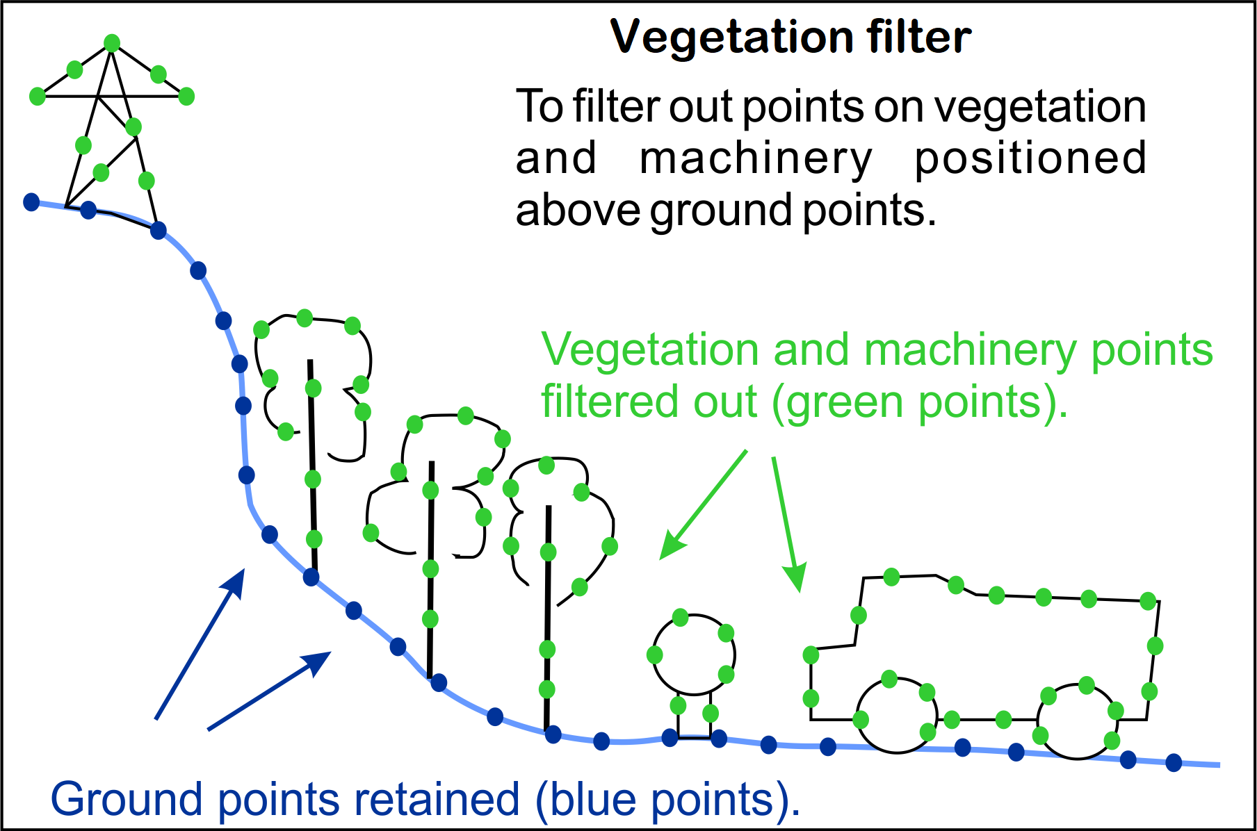
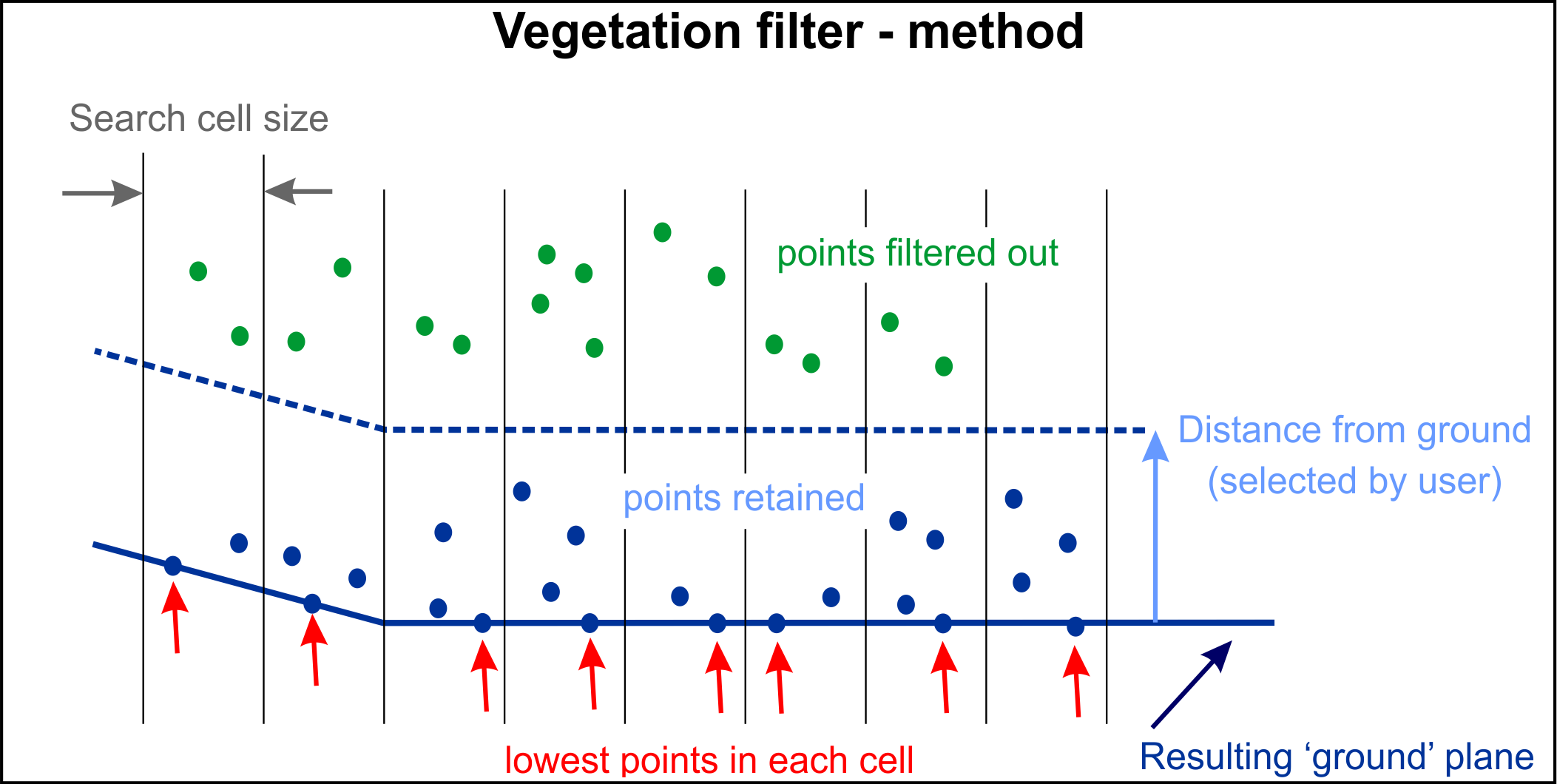
The Vegetation filter removes unwanted features such as plants and machinery from the ground planes of scans. As with the topography filter (see Topography), the vegetation filter divides the scan data into a horizontal grid with a defined cell size. The single lowest point in each cell is retained as the ground reference.
Note: The vegetation filter also results in more even point distribution.
-
To filter vegetation, follow these steps:
-
Create or select a polygon to use (see 2D Polygon and Polygon). Alternatively, you can create a polygon region from within the vegetation filter tool at step 8.
-
On the Position and Filter tab, in the Filter group,
 Vegetation from the Filters drop-down list select.
 -
Specify a Search cell size by entering a value or dragging the slider. The optimal cell size is typically between
0.5and2m. A cell size that is too large will round edges excessively.
-
Set the Direction towards ground to indicate the approximate orientation of the ground area to be filtered. Select one of the options from the drop-down list and specify its parameters, as follows:
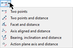

Two points
Define the direction and distance by specifying two points.

Two points and distance
Define the direction by specifying two points, then enter the distance.

Facet and distance
Make the direction perpendicular to a selected facet, then enter the distance.

Axis aligned and distance
Define the direction by an axis of the view window, then enter the distance.

Bearing, inclination and distance
Define the direction by a bearing and inclination angles, then enter the distance.

Action plane axis and distance
Define the direction by an axis of the action plane, then enter the distance.
You can populate parameter fields either by manually entering values, or selecting data in the project explorer or view window to complete values automatically.
-
Select the scans

 to be filtered in the project explorer.
 -
Click Next > to continue or < Back to go back.
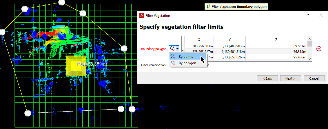
- Drag
the polygon from step 1 into the Polygon
field if it has already been created. Otherwise, create a polygon region
from within the Filter Vegetation
tool, using By points.
-
Select the required Filter combination (see Filter Combinations).
-
Once the perimeter limits are assigned click Next > to advance to the Preview and confirm vegetation filter page. Points to be filtered out will be highlighted red in the view window.
-
Enter a Distance from ground as tolerance level. Points in each cell within this distance from the ground reference will be regarded as ground points. Points outside this distance are to be filtered out.
-
If required, select Keep vegetation to reverse the filter so that points lower than the Distance from ground are removed. This is useful for cleaning up data in a tunnel or other underground void where items hanging from the ceiling may be unwanted and must be removed. See also Filter.
-
Click Finish to apply the filter or < Back to change parameters.
Important: Direction towards ground is needed for setting up cell orientations. It should point as close as possible to the average of planes forming the chosen ground area.
Tip: Use
 Bearing, inclination and distance to help with the alignment of the grid. Select the area to be filtered using
  (Select points) and the parameters will be completed automatically.
Adjust the Distance from ground until a satisfactory level of filtering is achieved.

-
The example below is an attempt to remove of trees and bushes from the scan data. Note, that the Distance from ground threshold still includes certain areas of ground material as well as trees and bushes in the selection to be removed. Any unwanted points remaining after the process must be manually removed.

Note: If the Distance from ground value is increased, the lower ground points are no longer included in the selection to be removed, but some vegetation points may also be retained.
Tip: You can redisplay filtered points
by clicking ![]() Show All. See Show All.
Show All. See Show All.
The Remove Object filter removes single persons, trees, vehicles or similar objects on fairly flat ground, or several nearby objects if they are on the same fairly flat surface.
-
To remove objects, follow these steps:
-
Using
 (Select points), select a small point selection in which the ground is relatively flat, but contains the object to be removed.
Note: This tool needs a high proportion of 'ground' points to work reliably. We recommend having at least as many points in the selection from a flat area of ground around the object as there are from the object.
-
On the Position and Filter tab, in the Filter group, select
 Remove Object from the Filters drop-down list. Based on the points selection, the Remove Object tool will:
- identify points belonging to the flat surface.
- identify points belonging to the object to be removed.
- model the flat surface.
- display a preview of the points and modelled surface in the tool panel.
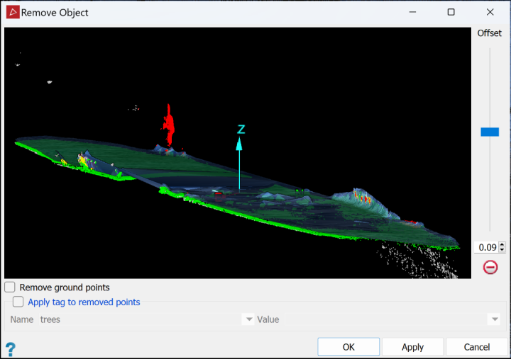
Red points are to be removed and green points are to be retained. Yellow points are object points between the modelled surface and ground. These will also be removed. White points are not included in the modelling and will be retained.
The modelled surface will be displayed, offset from the ground points by the distance set with the Offset slider.
Tip: You can zoom, pan and rotate the preview using the mouse buttons, as with manipulating the view window, except you don't need to hold down Alt.
-
It is possible that some points are wrongly identified for removal or retention. Adjust the Offset slider up or down to move the modelled surface and optimise ground point retention and object point removal.
-
If you want to retain the object and delete the surrounding surface points, select the Remove ground points checkbox.
Note: In this case green red colours are swapped in the previewer and only the new red (formerly green) points are removed, while all others are retained.
-
If necessary, apply tags to removed points.
-
Select Apply tag to removed points.
-
Select a tag from the Name drop-down list. If there isn't a suitable tag in the list, create one by typing a new name in the Name field.
-
Select a value for the tag from the Value drop-down list or type a new value in the Value field.
-
-
Click OK or Apply.
-
The specified points will be hidden from view.
Tip: You can redisplay filtered points
by clicking ![]() Show All. See Show All.
Show All. See Show All.
The Water Reflections filter identifies erroneous points in scans resulting from reflections in pooled water, applying an attribute name by which they are then hidden from view. You can use this attribute to reapply the filtering or for a different effect. See Attributes.
Note: The water reflections filter will only work on terrestrial scans with a grid topography, such as those taken with Maptek scanners.
Note: For the water filter to work correctly, horizontal axes of the scans should be parallel to the XY plane.
Note: The water filter works on whole scans regardless of any points-selections or whether you have filtered the selected scans previously.
-
To filter water reflections:
-
Select the scans

 to be filtered.
 -
On the Position and Filter tab, in the Filter group,
 select Water Reflections from the Filters drop-down list.
-
If required, change the attribute name.
-
Click OK or Apply.

Before (left) and after (right) removing water reflections
-
Tip: You can redisplay filtered points
by clicking ![]() Show All. See Show All.
Show All. See Show All.
