Surface
Source file: surface-group.htm
The Surface group provides miscellaneous tools for analysing surfaces.

|
|
Surface Volume (Alt+V) Calculate the volume between surfaces. |
|
|
Surface Validity Check for errors in creating a surface. |
|
|
Surface Intersections Identify intersections between surfaces or discontinuities. |
Surface Volume
The Surface Volume query (Alt+V) allows you to calculate the volume enclosed by two surfaces, or the volume between one surface and a plane at a fixed elevation.
Proceed as follows:
-
On the Query tab, in the Surface group, click
 Surface Volume.
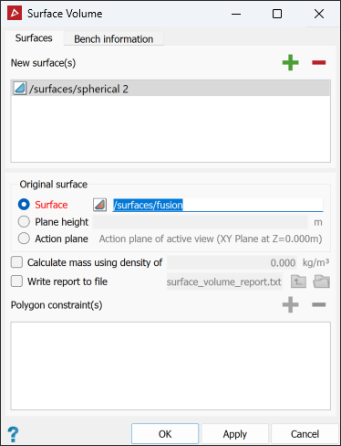
-
Drag the surface

 to be measured into the New surface(s) field.
 -
In the Original surface area, select one of the following as a reference for calculating the volume of the new surface:
- Surface: Drag the reference surface in from the project explorer.
- Plane
height: Enter the height of the reference plane.
Note: If a using a reference plane height, you can enter a Reduced Level (RL) manually, or pick a point selected directly from the model in the view window. PointStudio will create a horizontal plane at that RL.
- Action Plane: Uses the XY plane as the action plane of the active view.
Note: The volume is only computed in the areas where the two surfaces overlap, when viewed from above, or in the Z direction. The original surface should be a base model.
-
Select Calculate mass using density of and enter a density value if you require the results reported as mass.
-
Select Write report to file to save the results to a text file.
Tip: Alternatively, you can copy this information from the report window and paste it into a document.
-
To constrain calculations within certain boundaries, draw the boundaries as polygons (see Polygons) then add them to the Polygon field.
-
Go to the Bench information tab and select Surface volume by bench to generate a bench-by-bench breakdown of cut, fill, and volume differences.
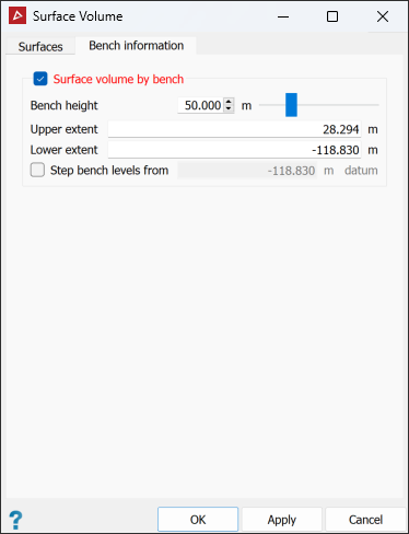
The Bench information tab enables the volumes to be broken down by bench.
-
Define the Bench height as the distance between bench levels.
-
Specify the required upper and lower extents for the contours if different from the automatically calculated values.
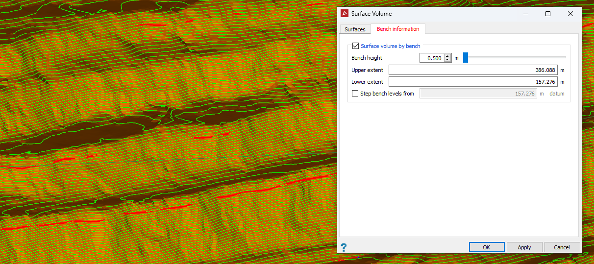
In the above example, the green lines represent the specified benches between which the volumes will be calculated.
-
Select Step bench levels from and enter the required starting bench height to step the bench levels from. Clearing this option will step the bench levels from the zero RL.
-
Click OK or Apply.
Note: The volume reporting units can be changed via the PointStudio Preferences in the Units tab.
The results are displayed in the report window.
Surface Validity
The Surface Validity query allows you to check for any problems with surfaces, such as holes or intersecting triangles.
Proceed as follows:
-
On the Query tab, in the Surface group, click
 Surface Validity.
 -
Select the surfaces

 to be checked.
-
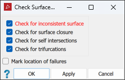
Select or clear the check options as required:
- Check for inconsistent surface to check that all facet normals are pointing in the same direction to avoid problems with calculating volumes and creating fusions.
- Check for surface closure to check the boundary edges. This is only applicable to closed solid surfaces; clear this for all other surfaces.
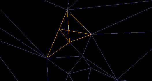
- Check for self-intersections to check for intersecting triangles on the surface, as shown below.
- Check for trifurcations to check for and find any edges with more than two facets sharing the same edge on a surface.
- Mark location of failures to create objects in the
cad container
that highlight the error locations.
-
Click OK or Apply. A written summary of the results will be displayed in the report window.
-
Drag any objects created in the
cad container onto the surface view window to display any errors
found.
To repair any errors found:
- Run the
 Fix Surface tool first. See Fix Surface. If necessary, continue with the next steps.
 - Zoom in to an error and display the surface
in wireframe
 .
.
-
Using
 (Select points) type, select
a corner point on the erroneous triangle and press Delete.
-
On the Edit tab, in the Fix group, click
 Fill Holes.
- Repeat steps 2–4 for all remaining errors.
Surface Intersections
The Surface Intersections tool enables you to create edge networks at the intersections of surfaces.
Proceed as follows:
-
Highlight two or more surfaces

 in the project explorer.
 -
On the Query tab, in the Surface group, click
 Surface Intersections.
PointStudio searches for surface intersections then opens the Check surface intersections panel.
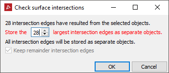
- Click OK to finish.
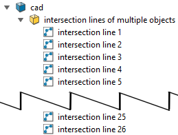
An edge network
is saved in a cad ![]() container named
intersection lines of surface1 and surface2,
or similar, depending on the number of surfaces queried. You can nominate
to store a number of the largest intersections as separate objects (named
intersection line 0, intersection line 1, etc.). The remainder are combined together into one object
named remainder.
container named
intersection lines of surface1 and surface2,
or similar, depending on the number of surfaces queried. You can nominate
to store a number of the largest intersections as separate objects (named
intersection line 0, intersection line 1, etc.). The remainder are combined together into one object
named remainder.
Tip: This tool is useful for determining differences between regions, particularly when solid volumes are not suited to the calculations. You can also use it for other options e.g. explode and then use one of the loops to crop by polygon.
|
|
|
|
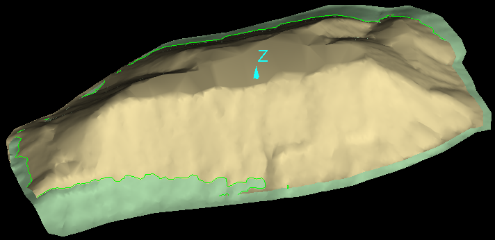
An example of a query result of two intersecting surfaces. |
|
