New Definition
Use this option to create a new block model definition file (.bdf). A block model definition file is used to define the construction of a block model.
You can also create a new block model definition file (.bdf) using the following options:
- To create a definition file using Vulcan Explorer, right-click on the Specifications folder in the Vulcan Explorer window and then click New Block Definition File.
- To create a definition file using the Block Model Utility, open the Block Model Utility, click File, then click New.
Instructions
On the Block menu, point to Construction, then click New Definition.
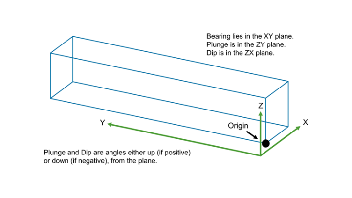
Orientation / Schemes
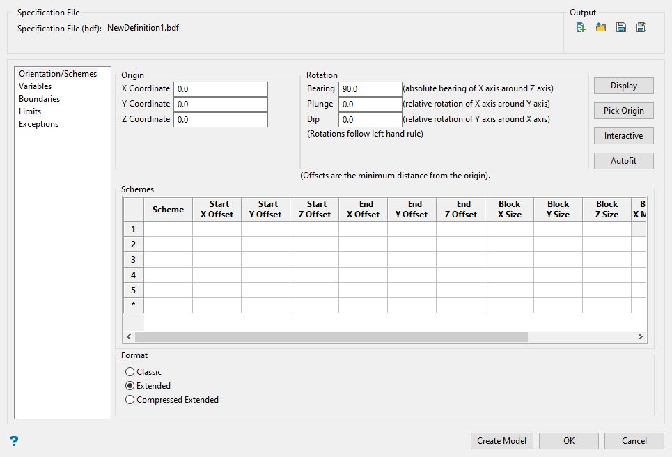
Use this pane to set the model origin, orientation, and block sizes.
Follow these steps:
-
Load all the data into Envisage that you will need to determine the boundaries of the block model. This may include triangulations, polylines, sample points, drillhole data or any other visual data that may help.
-
Click either the Autofit or Interactive button. This will display a panel allowing you to set the origin, rotation, and parent block size parameters. The same panel will be displayed for both options.
-
If you use the Interactive option, select the location for the origin.
Set the origin by selecting a location on the screen. This point is an arbitrary point used to define the starting location for measuring the offsets in the Schemes table and the pivot point for the rotations. The origin, offsets, and rotations are used in conjunction with the parent block size (described below) to define the position of the block model in space.
-
If you use the Autofit option, the origin will be automatically selected for you. It select a point with the minimum X, Y, and Z values possible to create a block model that encompass all your data.
Tip: It is helpful to use Autofit and let it set the location of the origin, then edit that location if necessary.
Once an origin has been selected, the Edit Interactive Block Model panel will be displayed.
-
-
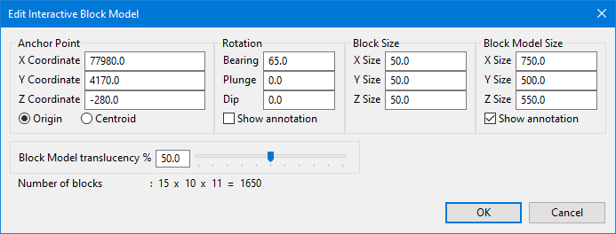
Confirm the Anchor Point. The anchor point will be shown as the origin point if Origin is selected, or the centre of all the loaded data if Centroid is selected. Note: If you select Centroid, it will not move the origin to the centre of all the data. This feature is only to help visualise and manipulate the extents of the block model more easily while using this panel.
TipWhen confirming the anchor point, a common practice is to round the coordinates up or down to eliminate the decimal places. The amount you round will depend on the size of the block model. For example, when using Autofit you may end up with coordinates showing a precision of three decimal places. There is nothing wrong with this, but calculating distances and offsets can be made easier by rounding, as shown here.
Original Rounded 77983.532 77880.00 4168.553 4430.00 -283.225 -280.00 -
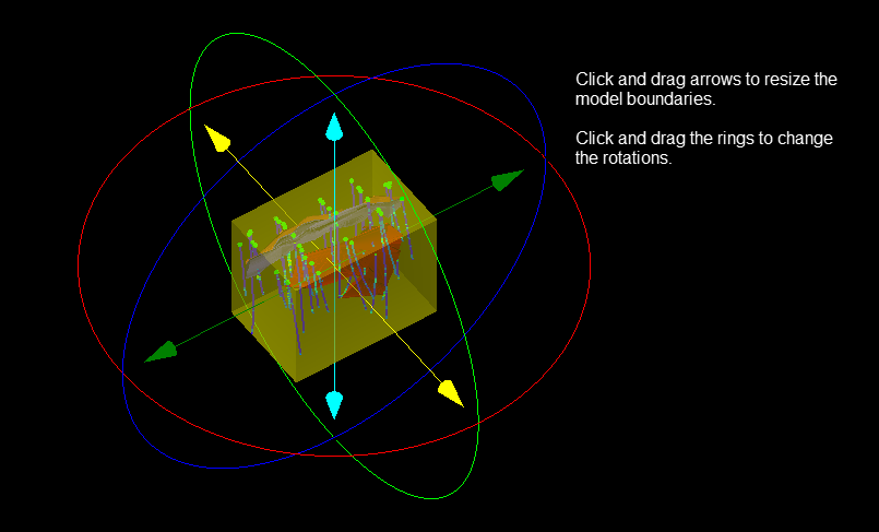
Set the rotation parameters for Bearing, Plunge, and Dip. You can do this by entering the numbers manually, or by clicking and dragging the arrows and rings on the screen.
-
Set the parent Block Size. This defines the maximum block size over the domain of the model. Most of the time this will reflect the SMU (Smallest Mining Unit). It will also determine the smallest increment that will be used when setting the Block Model Size. As seen from the screenshot of the Edit Interactive Block Model panel above, we are using a parent block size of 50 x 50 x 50 in our example. That means the size of the block model for the X, Y, and Z directions will increase or decrease in size in increments of 50.
To make your data easier to see, use the Block Model Translucency % slider to adjust the transparency of the block model extents.
As you make adjustments, the Number of Blocks will be displayed, letting you know the current dimensions of your block model.
-
Click OK to return to the main panel.
-
Set up the minimum and maximum size of the blocks by entering the information into the Schemes table.
 Explanation of Schemes
Different schemes allow you to define the blocking constraints for a model. A scheme is a list of specifications for the extent of the blocks and their size. By default, there must be a Parent scheme that contains a parent cell size that defines the maximum cell size over the domain of the model, and there can be only one parent cell size used in a block model. If you used the Edit Interactive Block Model by clicking the Autofit or Interactive buttons, the parent size will already be filled out for you.
You can set up additional block sizes by creating sub-block schemes. The dimensions of a sub-block can be any size as long as it fits evenly inside of the parent block.
Example: Using a parent block size of 50 x 50 x 50, a sub-block size of 20 x 20 x 20 would not be allowed since 20 is not a multiple of 50 and does not fit evenly inside. However, using a sub-block size of 25 x 25 x 25 would be allowed since 25 is a multiple of 50, and therefore fits evenly inside of the parent block.
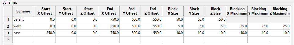
Sub-blocking splits a parent block into smaller blocks that follow geological boundaries with greater precision. You can specify a number of sub-blocking schemes, allowing different regions of your block model to have different block sizes, as shown in the Schemes table example above.
-
Enter the name of the parent scheme.
The first row in this table is always used to define the parent scheme, with subsequent rows being used to define the sub-block areas.
-
Enter the offset distances. These distances are relative to the origin point. The Start Offset defines where the sub-block scheme will be measured from, and the End Offset indicates how far that scheme will extend.
Example: In the example above, the sub-block scheme named
westwill limit the block sizes to be no more that 25 units in the X, Y, and Z directions, and have a minimum size of at least 5 units. The sub-block scheme namedeastwill limit the block sizes to be no more that 10 units in the X, Y, and Z directions. Note: The units can be either Metric or Imperial, and are set in Vulcan Preferences > Miscellaneous. -
Enter the dimensions for Block X/Y/Z Size. This is the minimum size that a parent block can be divided. For the parent block scheme, it is the only size that can be used.
Our example above shows a parent block size that is equal on all sides. However, this is optional. A parent block does not need to be equal on all sides. A common practice is to set the Block Z Size equivalent to the bench height in an open pit, while making it less for stratified deposits such as coal seams.
-
Enter the dimensions for Blocking X/Y/Z Maximum. This is the maximum size that a sub-block can be. It cannot be larger than the parent size, and it must have a dimension that can evenly fit inside of a parent block.
-
-
Select the format for the block model.
Classic
Extended
Compressed Extended
Data allocation All data must be allocated when the block model is constructed. No data is stored when a block model is created. Disk space is dynamically allocated when values are stored into blocks. Same as Extended.
Block model blocks Restricted to 2 x 10⁹ blocks. Can exceed 1018 blocks Same as Extended.
Indexing You require an amount of free disk space that is equal to the size of the actual block model.
For example, if the block model is 4 Mb in size, then you will need to have a minimum of 4 Mb free disk space in order to perform the index procedure.No extra disk space is required in order to perform the index procedure.
In a regular extended model the index is not stored, but is implied, so the model is always indexed.
In a sub-blocked extended model the index is stored in such a way that it does not need to be rewritten, so the model remains indexed.Same as Extended.
Miscellaneous Models can be created very quickly.
Model may contain a large number of blocks, well in excess of 4 billion blocks.
Variables may be added and removed quickly.
Disk space is only used for block values which are stored.This format works best with block models that have a lot of categorical variables, as opposed to variables that are estimated.
Variables
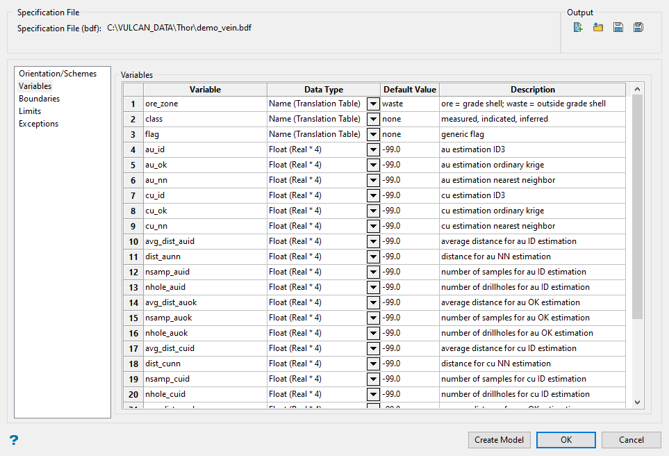
In this section you will define the variables in the block model. These variables may be data fields represented by triangulations, assay values, or any other category contained in the model.
Selecting the appropriate data type for the information, particularly with large files, can save significant disk space. Before creating a block model you need to think carefully about what variables you will require. For example, do you need variables for air or rock, or maybe a set of geological variables stating which geological zone it is in?
General guidelines:
- The maximum number of variables per block model is 300.
- The name of a variable can have a maximum of 30 alphanumeric characters.
- A variable name must start with a letter and can only contain alphanumeric characters and/or underscores, for example, '
variable_1. - A variable name can only be entered using lowercase characters.
- Variables to be used as the estimated grade in grade estimation must be of a float or double data type.
Variable naming conventions vary from company to company. Some companies use variable names that are quite descriptive while others are not so clear. That is why the Description column is so important.
There are six data types to choose from:
- Name (Translation Table)
- Byte (Integer*1)
- Short (Integer*2)
- Integer (Integer*4)
- Float (Real*4)
- Double (Real*4)
The Default Value is the value given to a variable that has not been assigned any value yet. It is highly recommended that the default value assigned to a variable not be true values that could actually be found or calculated in a real scenario. For alpha data types a default of none works well, and for numeric data types -99.0 works well.
-
Enter the names of each Variable (a maximum of 30 alphanumeric characters). A variable, which can only be entered using lowercase characters, must start with a letter and can only contain alphanumeric characters and/or underscores, for example,
variable_1.Note: There is no limit regarding the number of variables that can be added to a Maptek Vulcan block model. However, at least one variable must be defined for a block model to be created. The memory capacity of your computer and the overall size of the block model will determine what the maximum number will be.
-
Select the Data Type from the drop-down list. The following data types are available.
Data Type
Description
Name (Translation Table)
This is used for character type data. The description is entered in the Description field. A translation table is automatically created that links any defined character codes to numeric values that are stored in the block model.
Byte (Integer * 1)
This uses a single byte of memory. Using the byte data type saves significant memory particularly if you have a rock code that is an integer in the range 0-255.
Short (Integer * 2)
This is a short integer taking two bytes of memory in the range -32768 to +32767.
Integer (Integer * 4)
This is a fixed point number (-2,000,000,000 to +2,000,000,000) taking up 4 bytes.
Float (Real * 4)
This is a real number taking up 4 bytes. It is generally used for single precision numerical data codes such as grades and densities - up to seven significant figures.
Double (Real * 8)
This requires two consecutive storage units (taking up 8 bytes) providing greater precision than real number types and is used for numbers up to 14 significant figures.
Important: Variables to be used as the estimated grade in grade estimation must be of a float or double data type.
-
Enter a Default Value for each variable. This value will be assigned to the variable when a block has not been estimated. The following characters may be used in combination with the default value, but not on their own: [ ] ( ) { } %, + - * / &.
TipWe recommend that the default value is not a true value, that is, that the default value does not occur naturally in the block model. The reason for this is that in reserves reporting, default values are reported as an "unknown" category.
If you assign 2.8 as the default value for SG, and 2.8 happens to also be the global block SG value, then the reserves calculation will report the 2.8 values in the wrong category (the "unknown" category). It is therefore better to use a default value that doesn't occur in the block model, such as -99, and then run a script to reassign all blocks that need to have a value 2.8. This way the blocks with SG = 2.8 will be reported in their correct category. Byte and short data types must not have a negative default value.
-
(Optional) Enter a description of the variable. There is a 40 character limit for each description.
Boundaries
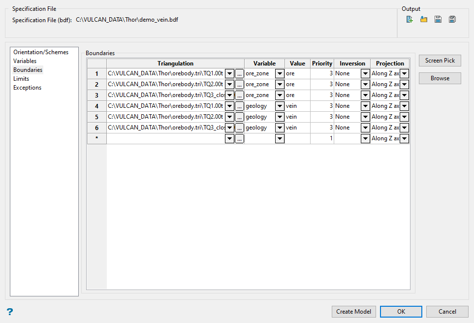
Use the Boundaries section to define how triangulations are used in your block model.
There are two main ways that triangulations are used in a block model:
-
Defining the boundaries of the sub-blocking scheme.
Sub-blocking is performed along defined boundaries. They are calculated to achieve maximum resolution using the minimum sub-blocking size nominated. Wherever possible, sub-blocks are coalesced into larger blocks related to the maximum size of the parent block.
-
Defining what variables will have values assigned when the blocks are created.
In addition to assigning values to variables during the estimation process or by running a script, variables can be assigned values when the blocks are initially created. For example, if you have a topographic surface you can assign a value of
airto all blocks that are located above the surface, andgroundto all blocks that are located below the surface. Another example might be defining geologic formations based on triangulation solids representing different stratigraphic layers. The block values are based on whether a block centroid occurs inside or outside, above or below nominated triangulations. You can select your triangulations individually of by using selection files.
-
Select a triangulation surface or solid that you want to use as a boundary for sub-blocks or as a domain in which to assign values to a variable. The drop-down list contains all triangulations in the current working directory. Click
 to select a file from another location. You can also select selection files (.sel) or Pre Version 4.x selection files (.sms) from the Open dialog panel by clicking the Browse button.
Note: You can only assign one value to one variable per triangulation on any given row in the table. However, you can use the same triangulation on multiple rows to assign different values to different variables. For example, the same three vein solids are being used in the example above to define the variables
ore_zoneandgeology.
-
Select the variable that will be assigned to the triangulation. The variable is used to store the value assigned by the triangulation. Each triangulation may be assigned the same or different variables. For example, a series of triangulations may define the geological zones of the model and another series may define the weathering or alteration zones of the model.
-
Enter the value that will be stored in blocks with respect to the inversion rules used for this triangulation. This is the value that will be assigned to the block if it is found in the influence area of the triangulation. The value must match the variable type. Only lowercase characters may be entered.
-
Specify the priority for the variable (the default value is '1'). The higher the number, the higher the priority (a priority of 10 overrides a priority of 1).
This is used to determine precedence if two or more triangulations are being used set different values in the same variable. Wherever there is a spatial conflict between the triangulations, the one with the highest priority takes precedence.
-
Specify the desired level of inversion. Select None (no) inversion, Partial inversion, or Complete inversion. Partial inversion has not effect for 3D triangulations.
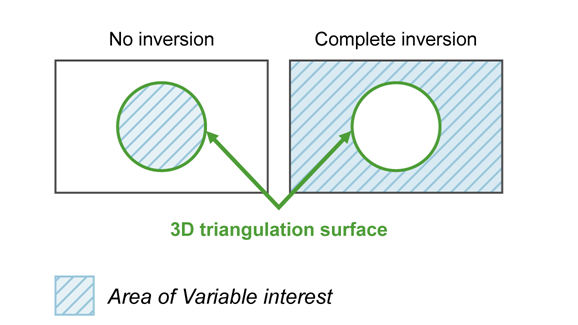
Figure 1 : 3D Triangulation Inversions
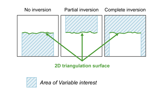
Figure 2 : 2D Triangulation Inversions
-
Select the projection axis. The projection axis defines the direction for a surface and has no effect when working with solids. This option is used in situations where steeply dipping structures define regions.
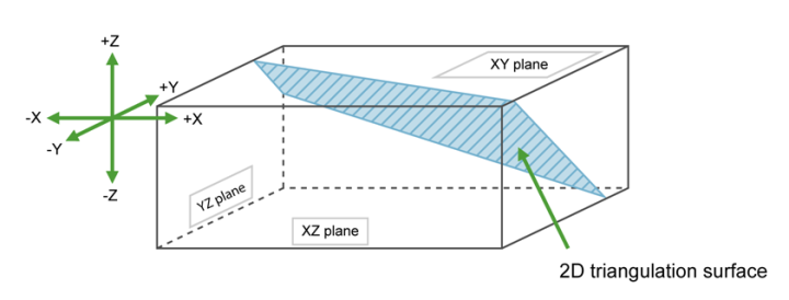
Figure 3 : Projection Axes
If No inversion is selected, the negative side of the triangulation is the area of interest. If Partial or Complete inversion is selected, then the positive side of the triangulation is the area of interest.
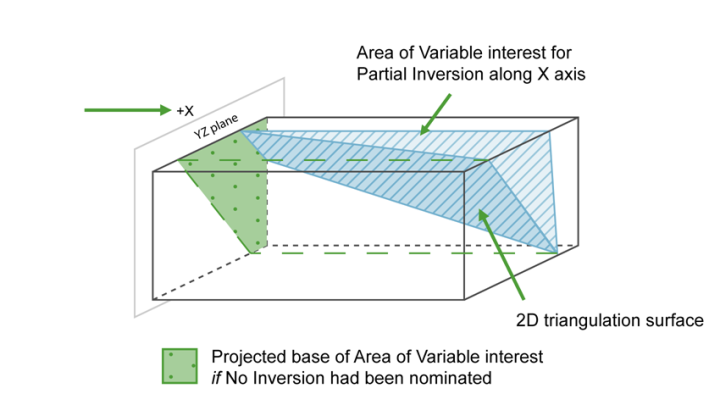
Figure 4 : Projection along the X Axis.
For triangulations (ore bodies) that are steeply dipping, it may be necessary to project along the X or Y axis to ensure the correct inversion is applies.
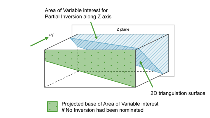
Figure 5 : Projection along the Y Axis
For triangulation (ore bodies) that are near to horizontal (lying in the XY plane), you would project along Z axis. The area of interest is then below the triangulation (if None (no inversion) is selected) or above (if Partial or Complete is selected).
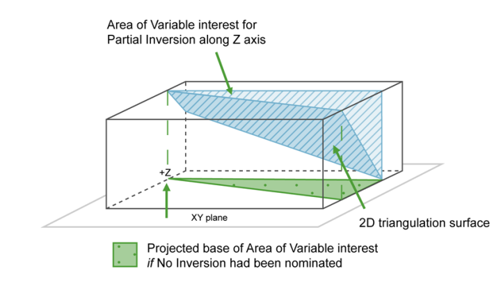
Figure 6 : Projection along Z Axis
-
Click the Limits tab in the menu tree to continue.
Limits
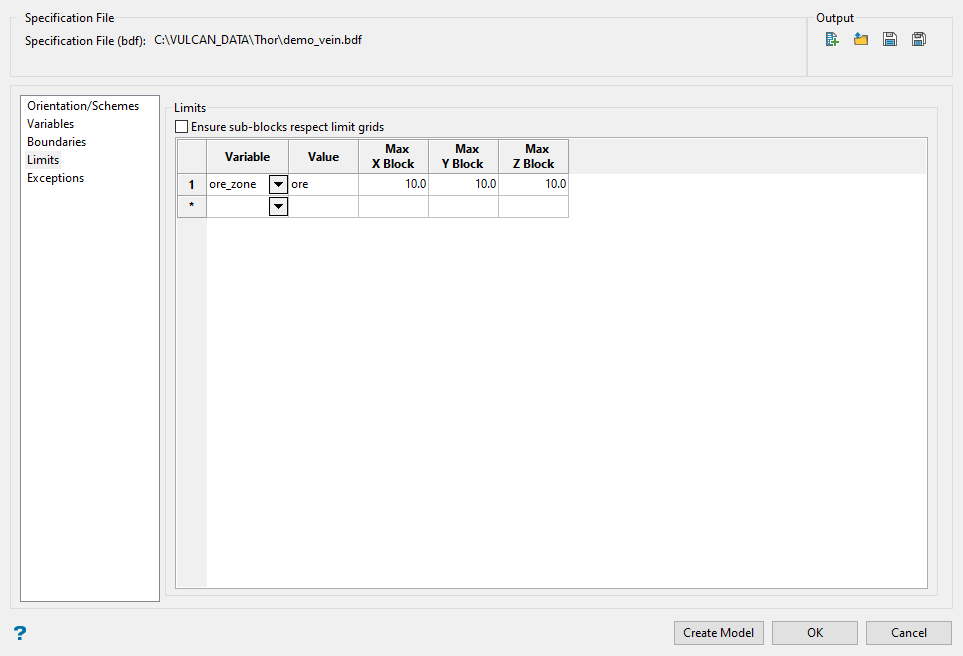
Limits are optional and allow you to restrict the size of blocks that are built in a specified block model area.
A limit is defined by a value in a particular variable, and a maximum X, Y and Z size for restricted blocks.
In the example shown above, a limit was used to set a maximum block size. Any block in which the variable ore_zone has a value of ore will have a maximum block size of 10 x 10 x 10. In all other cases, the blocks will be sized according to the parent and sub-block settings.
Limits are also used to help deal with the problem of increasingly large block models. Models can get increasingly larger as variables are added and populated. One method of reducing model size is to make larger parent blocks in areas of lesser importance such as waste and air, and smaller parent blocks in areas of mineralisation.
The parent blocks chosen in the mineralisation are based on the drill spacing and intended mining SMU. From a statistical viewpoint, when smaller blocks are regularised to an SMU, it is appropriate to coalesce the volume and grade of the smaller blocks to a larger regular block.
-
Select the variable you want to use to limit the block sizes.
-
Enter the value of the variable to which the limit applies. The following characters may be used in combination with the value, but not on their own [ ] ( ) { } %, + - * / &.
-
Enter the maximum block sizes for the X, Y, and Z directions. All blocks will be limited to this size if the value in the selected variable matches.
Note: The maximum block size cannot be less than the minimum block size (set through the Schemes section).
-
Click the Exceptions tab in the menu tree to continue.
Exceptions
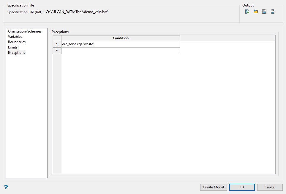
This section allows you to assign conditions in which blocks will not be created. Those conditions are called exceptions.
A condition is based on the value a selected variable is given during the creating of the block model. When a variable is populated during the creation of the block model, we can use that information to flag a block and assign a conditional statement based on one or more possible values.
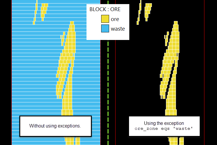
In our example, we added the exceptions ore_zone eqs 'waste'. This means that any block in which the variable ore_zone has a value of waste was not created, as shown here.
-
Enter the condition, which can relate to any of the defined variables in the block model. The maximum size of the condition is 132 alphanumeric characters, for any longer conditions you need to edit the Block Definition File (.bdf) manually. The usual mathematical operators can be used, see Appendix B for a list of Operators and Functions.
You can have multiple exceptions.
-
Click the Save icon
 .
. -
Click Create Model to begin the build process.

