Polygon Flag
Use this option to flag a block model variable based on whether or not the block centroid is within a selected polygon.
Instructions
On the Block menu, point to Manipulation, then click Polygon Flag.
| Polygon Flag | Flag 2D Polygon |
|---|---|
|
|
General tab
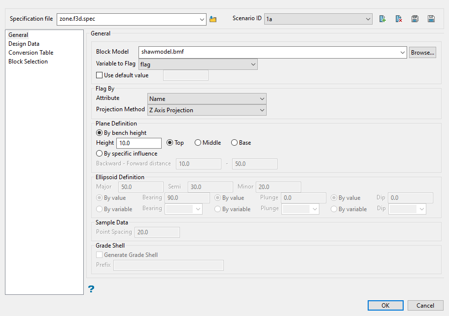
Follow these steps:
-
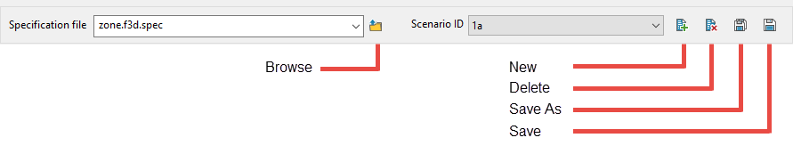
Select a specification file. Use the drop-down list to select the file if it is in the current working directory, or browse for it in another location by clicking the Browse icon. To create a new specification file, type the name of the file into space labelled Specification file.
-
Choose a Scenario ID from the drop-down list to load preset values stored into the current specification file.
Each specification file can have multiple scenario IDs associated with it. Having multiple IDs in one specification file can be useful to run a batch process when required.
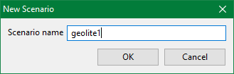
To create a new ID, click the New icon and enter a name into Scenario name.
Click OK. You will be navigated back to the Polygon Flag panel. Click the Save button.
-
Choose the block model file you want to use from the Block Model list, or click Browse to select the specification file from another location.
-
Select the block model variable from the Variable to Flag list. This will be used to store the flagged value.
Note: If Use default value is selected, the default value set up in the block definition file will be stored in the variable when a block is not in a selected polygon. To use a value other than the default value, clear the Use default value check box and enter the value.
-
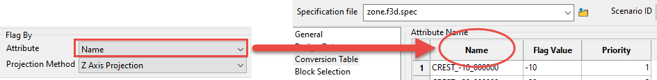
Select the polygon attribute to flag by from the Attribute list. You can select colour, name, value, group, feature, or layer name. This will help you to group all the attribute values between the selected polygons and decide the flag values for each attribute.
-
Select the projection method to flag by from the Projection Method list.
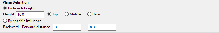
For X Projection, Y Projection, Z Projection, and Orthogonal to polygons, use Plane Definition to set up the flagging parameters.
-
Use By bench height if the layer used to flag the blocks can contain multiple polygons, such as the output from the Automated Pit Designer.
To use By bench height, enter the Height, then select Top, Middle, or Base to represent where the polygon intersects the bench height.
-
Use By specific influence if the layer used to flag the blocks contains a single object, such as a boundary polygon surrounding an area of interest. This will give you greater control regarding which blocks will be flagged because you can adjust the depth of influence.
To use By specific influence, enter the Backward - Forward Distance to set the distance of influence both in front of and behind the polygon.
-
-
Use Ellipsoid Definition to set up parameters for using By Ellipsoid by specifying the bearing, plunge, and dip of the search ellipsoid. You can enter the values in directly or use a variable from the block model.
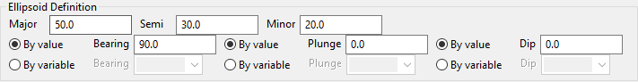
Note: The Ellipsoid Definition section is only available if the By Ellipsoid option is selected in the Projection Method.
Note: If the plunge is for a downward pointing ore body, the plunge value should be a negative value.
 Bearing, Plunge, and Dip
The Bearing, Plunge, and Dip values are angles, in degrees, that specify the orientation of the search ellipsoid and orientation of variogram structures.
Care must be taken with these parameters as there are several common misunderstandings about their meaning.
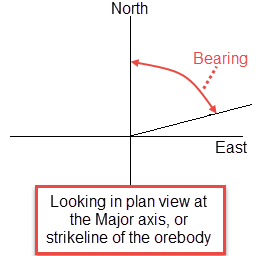
Bearing
Bearing is the angle of the Major axis as it rotates clockwise from the north. It is the angle of the strikeline of the orebody.
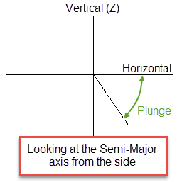
Plunge
Plunge is the angle of the Semi-major axis as it rotates around the minor axis. Note that the plunge should be negative for a downward pointing ore body.
Dip
Dip is the angle of the minor axis of an orebody as it rotates around the Major axis. Think if it as the angle that an orebody tips from side to side when looking down the strikeline.
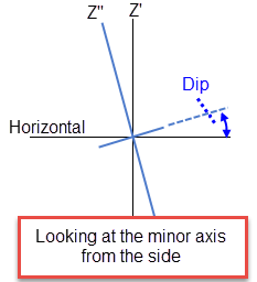
Note: The terms bearing, plunge and dip have been used by various authors with various meanings. In this panel, as well as kriging and variography, they do not refer to true geological bearing, plunge, and dip. The terms X', Y', and Z' axis are used to denote the rotated axes as opposed to X, Y, and Z which denote the axes in their default orientation.
-
Enter distance between samples in Point Spacing.
Note: This only needs to be done if you are using Ellipsoid Definition.
-
Select Generate Grade Shell and enter the Prefix that will be used for the name of each grade shell that is generated. (Optional)
Design Data tab
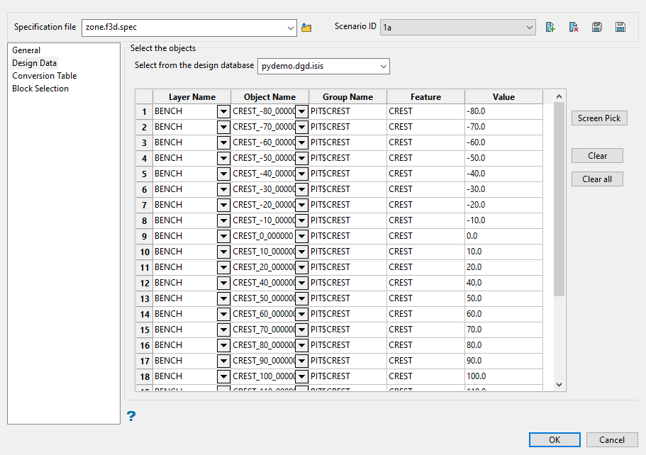
Use this panel to select the polygons that you want to use.
Follow these steps:
-
Choose a database from the Select from the design database drop-down list to load design data.
-
Select the Layer Name from the drop-down list. Alternatively, click the Screen Pick button to select object(s) from the screen.
-
Select the Object Name. The fields for Group Name, Feature, and Value will be populated automatically by drawing on information stored in the layer.
Note: You can store object information by using the option Design > Feature Edit > Feature Editor.
To remove an object, select the object and click the Clear button, or click Clear all to remove all objects from the list.
Conversion Table tab
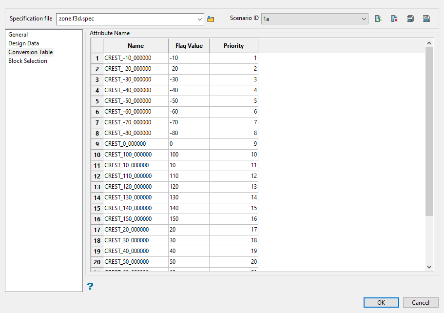
Use this panel to set up the values for the flagging variable.
Follow these steps:
-
Enter the value of the attribute (layer name, feature, group, value, or name) in the Value field, or select a colour in the Colour field.
NoteThis tab displays different column headings depending on which Attribute is selected in the Flag By field on the General.
-
Enter a value in to the Flag Value field if you do not want to use the default value. This is the value that will be added to the flagging variable in the block model.
-
Set the Priority for each object. The lower the number, the higher priority the object will have.
Block Selection tab
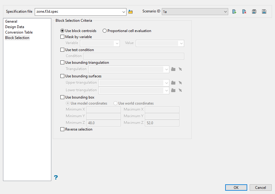
Use this tab to select which blocks will be flagged.
All the parameters on this tab are optional.
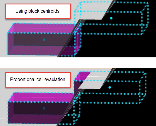
Decide whether you want to use the entire block in the calculations or only the portion that is within the regional boundaries. By default, the evaluation method is set to Proportional cell evaluation; however, you can select between Proportional cell evaluation and Use block centroids. This is especially important when using options such as Bounding triangulation, Bounding box, Section thickness, or Bounding surfaces.
Select the Mask by variable check box if you want to restrict the blocks by a block model variable. You will need to select the variable and value to mask by from the Variable and Value drop-down lists.
Example: To restrict blocks to those where Material equals Ore, select Material as the variable and Ore as the value. The block model variable may be alpha or numeric.
Select the Use test condition check box if you want to use a further constraint upon a numeric block model variable and enter the condition in the Condition field. The maximum size of the condition is 132 alphanumeric characters. (See Vulcan Core Appendix B topic for a full list of available operators and functions.)
To select only blocks that have an iron value greater than 10.0, you would select the Use condition check box and enter:
Fe GT 10.0
in the Conditions field.
Select the Use bounding triangulation check box if you want to restrict the blocks by a triangulation. You will be required to specify the bounding triangulation. Select the triangulation to use from the Triangulation drop-down list, or click Browse to select a triangulation from a location other than your working directory.
Note: This option is not applicable to open or 2D triangulations.
Select the Use bounding surface check box if you want to restrict the blocks by bounding surfaces. If you select this option, you must select the Upper triangulation and Lower triangulation from the drop-down list, or click Browse to select a triangulation from a location other than your working directory.
Select the Use bounding box check box if you want to restrict the blocks by a box. If you select this option, you must enter the minimum and maximum coordinates for X, Y, and Z in the Block model coordinates (X. Y, Z CENTRE) should be used section.
Select the Reverse selection check box if you want to exclude the selected blocks.
Be sure to save any edits done to the panel by clicking the Save icon, then click OK to begin flagging your block model.

