Create Unfolding Model
The Unfolding option is used in the grade estimation and variography of deformed strata bound deposits. This can be applied to deposits where mineralisation is controlled by a structural surface that can be modelled.
In unfolding, the grade estimation search ellipse, or variography search ellipse, is distorted from the usual shaped ellipse to follow nominated surfaces.
The benefit of using distorted search ellipses is that the block model stays in the position that it was created and the samples stay in their true position.
Instructions
On the Block menu, point to Unfolding, and then click Create Unfolding Model.

Steps for unfolding:
-
Enter a name for the specification file in Specification File (.tetra). You can also select one from the drop-down list, or click the Browse
 icon to select one that is located outside your current working directory.
At any time, click the Save
 icon to save all the setting on the panel.
 -
Choose the type of unfolding model you want to create by selecting from Unfold model type. There are three methods to choose from:
 Explanation of Projection Model
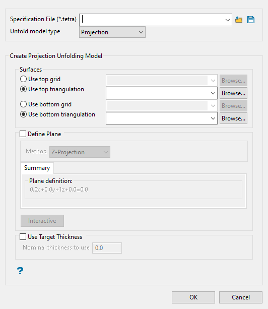
Use Projection Model to create a projection model by specifying two surfaces, either as grids or triangulations. Each point is transformed such that the X and Y coordinates are maintained. The Z coordinate is transformed such that points on the bottom surface have a transformed Z value of 0 and points on the top surface have a transformed Z value of '1'. A point exactly halfway between the top and bottom surfaces has a transformed Z value of '0.5'.
The unfolding model does not itself store the contents of a triangulation or grid. Therefore, any changes to a triangulation or grid will be reflected in the unfolding model whenever it is used.
If triangulations are used, they must not contain overhangs. Each X and Y coordinate must have one Z elevation on the triangulation. If the top and bottom surfaces have the same elevation, then the point is transformed to an elevation of '0.5'.
If a triangulation or grid has no Z elevation about a particular coordinate, then it will be treated as an elevation of '-999'. If both surfaces are missing, then both Z coordinates will be treated as '-999', which will result in the transformed point having an elevation of '0.5'. Usually both surfaces cover the planar area which is being estimated.
Typically, all your sample data and estimated blocks will be between the top and bottom surfaces. However, this is not a requirement. Points above the top surface will have Z coordinates greater than '1' and points below the bottom surface will have Z coordinates less than '0'. This feature can be used by starting with a triangulation, and then making a copy of the triangulation, transformed vertically by 1m. Use the original triangulation for the bottom surface and the new triangulation for the top surface of the unfolding model. This will result in the Z coordinates being translated by the elevation of the original triangulation, with no scaling.
When setting up the grade estimation parameters with unfolding, plunge and dip values are set to zero.
The major and semi-major radii will correspond to the distances as projected in the XY plane. This means that the major and semi-major radii will often be of the same order of magnitude as radii used without unfolding. However, they will not necessarily be the same values. If you look at a range of 10 metres with a plunge of 45°, the range as projected to the XY plane will be 10 cos 45, which is about 7.
Parameters for computing variography also need to take into account unfolding. Because the Z coordinates are typically transformed to be between '0' and '1', usually elevation angles are going to be small. Thus it is reasonable to perform variography over a small range of elevation angles. If your data spacing is about 10m, it may be reasonable to perform variography with elevation angles ranging from -6 to +6°. Also, consider using numbers of the order of '0.01' or '0.1' for the vertical tolerance. When computing variography for the vertical direction you will usually need to use an increased vertical angular tolerance.
 Explanation of Bend model
Use Bend Model to locate samples near a point in space and to establish the relative position of the samples to that point as well as to each other. The relative positions are not the standard Euclidean coordinates but are instead based on distances between the surfaces that define a seam or ore body.
 Explanation of LVA model
LVA unfolding works differently from the other forms of unfolding in that it uses two options together. First, an anisotropy model is needed, such as can be created by using Block > Unfolding > Create Anisotropy Model.
Note: The Anisotropy Model is separate from the (.tetra) file created by using the Block Unfolding options Bend Model, Projection Model, and Create LVA Model.
As part of the unfold model definition for the LVA model type, you are required to define distances in the major, semi-major and minor axis. These are used to establish ratios between the distances in those directions, as opposed to the actual search distances to be used in grade estimation. For this reason, if the three axes were defined as 100 m x 50 m x 10 m, it would yield the same ratio as if they were defined as 50 m x 25 m x 5 m in this panel.
The actual search distances used for the estimate depend on the search distances defined in the grade estimation setup. When unfolding is selected as part of the grade estimation and the LVA (.tetra) file is chosen, the ratios calculated there are applied to the largest of the three search distances that have been defined in the grade estimation panel; this typically being in the major axis direction. It is from the application of these ratios to the largest distance in the panel that the other two shorter search distances (typically the semi-major and minor) are calculated. These search distances are used for the estimation. The two shorter distances defined in the estimation setup are effectively ignored in preference of those calculated using the ratios from the (.tetra) file applied to the largest distance.
The parameter inputs will be different for each unfolding model type.
-
Setting up the parameters for unfolding models
 Setting up a Projection Unfolding Model

-
Select a top and bottom surface. You can use either a grid or triangulation. All available files that are stored in your current working directory will be displayed in the drop-down menus.
-
Define the projection plane by selecting the method from Method drop-down list.
Line Segment
Select this option to define the plane by selecting an existing line and specifying the dip. Only design strings may be picked and it is not possible to pick a line in an underlay. The direction of the view, and therefore the direction of the stepping, depends on the digitised sequence of the line. The digitised sequence of the line can be reversed using the Design > Object Edit > Reverse option.
Two Points
Select this option to define the plane by digitising two points and specifying the dip. To locate a point precisely, use the Snap to Objects  or Snap to Points
  modes on the Digitise toolbar. Points may be snapped onto underlays, such as block model slices or triangulations. If you use Indicate mode
  to select the points, then the points have the current default Z value.
Select by 3 points
Select this option to define the plane by digitising 3 points. To locate a point precisely, use the Snap to Objects
 or Snap to Points
  modes on the Digitise toolbar. Points may be snapped onto underlays, such as block model slices or triangulations.
Using this option will allow you to explicitly define the location and orientation of a plane by indicating 3 points. The first two points define the bearing of the plane, and the third point defines the dip of the plane.
Y-Projection
Select this option to enter a specific Northing value (Y value). There are two ways to enter the Northing value; you can enter it directly into the text box, or you can select the Digitise icon, which to select a point from the viewing window.
X-Projection
Select this option to enter a specific Easting value (X value). There are two ways to enter the Easting value; you can enter it directly into the text box, or you can select the Digitise icon, which to select a point from the viewing window. The resulting section has a constant Easting (X) value.
Z-Projection
Select this option to enter a specific Level value (Z value). There are two ways to enter the Level value; you can enter it directly into the text box, or you can select the Digitise icon, which enables you to select a point from the viewing window.
Interaction
Select this option to manipulate an on-screen ellipsoid to define the plane. Click the  button to begin.
-
If you want to set a minimum thickness, enable Use Target Thickness, then enter a thickness into Nominal thickness to use.
Tip: A recommended thickness would be the average distance between the top and bottom surfaces.
If this option is not used, the thickness of the unfolded band is normalised between 0 and 1. This can have an effect on the vertical tolerance applied to your variogram. Some drillholes may be interpreted as being nearly horizontal.
Example: If you calculate a variogram using 5 degrees of plunge tolerance, you may be calculating an omidirectional variogram only because 5 degrees is almost vertical in real life. However, setting the nominal thickness to 200ft thick, you can set unfolding to produce a 200ft thick environment which will retain a more reasonable unfolded coordinate system.
Click OK.
 Setting up a Bend Unfolding Model

-
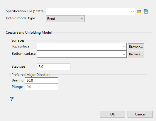
Specify the Surfaces that will be used to perform the bend unfolding. The drop-down lists contains all triangulation found in your current working directory. Click Browse to select a file from another location.
-
Enter a Step size. You can control the size of the step Bend unfolding uses to create the surface. If the faces of triangulations you use are on average 5 metres long, then it is reasonable to use a step size of '5'. Smaller step sizes increase the time needed to construct the surfaces, but may be necessary if the top and bottom surfaces have sharp bends. The following diagram shows the determination of the unfolded coordinate for a point. The unfolded coordinate is (10,-5,z).
-
Enter the Preferred Major Direction unfolding assigns X and Y coordinates to the surface by extending X and Y vectors starting at the centre. The bearing is the angle clockwise from north to the bearing line.
Plunge is the angle between the horizontal plane and the ore body axis. Note that the plunge should be negative for a downward pointing ore body.
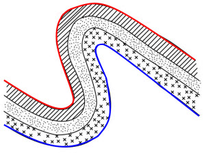
Note: Plunge and Dip values are set to zero when using Grade Estimation with unfolding, and the options are disabled. The terms “top” and “bottom” imply that the top surface is above the bottom surface, however, in the case of the Bend Model option there is no implied spatial relationship between the surfaces. For example, the bottom surface” could be above the top surface, or in a twisted relationship where it is sometimes above bottom and sometimes below.
The following image illustrates how the top surface (red) and the bottom surface (blue) can have an arbitrary relationship. Neither surface is above the other, but these are valid surfaces for bend unfolding.

Click OK.
 Setting up an LVA Unfolding Model
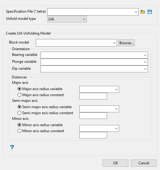
At a minimum, the bearing, plunge, and dip variables in the selected block model must be defined and populated prior to running LVA. You can also pre-populate the semi-major and minor axis radii for use in the panel.

-
Enter or browse for the block model that is being used for the unfolding process and contains the variables used in the panel.
-
Select a pre-populated variable for the bearing, dip, and plunge. One way to populate the blocks with these values is through Block > Unfolding > Create Anisotropy.
-
Enter a Major Axis. A major axis radius will need to be input as a constant value.
-
Select whether to use a pre-populated block model variables (which can vary throughout the block model) or specify a numeric constant radii (which is the same at all locations in the block model) for the semi-major and minor axes.
-
Click OK.
The (.tetra) file is created and can be used in variography and/or estimation panels.

