Slice
Use this option to create a standard slice through a Vulcan block model, allowing you to display an index of all the blocks that make up the slice or intersect that plane. The resulting slice can be displayed as underlay, saved in a layer, or output to a nominated block slice file (.bsf).
This option can also be accessed through the Vulcan Explorer application. Simply right-click on the block model name, then click the Slice option from the context menu.
You can also dynamically section the block model by using the Block > Viewing > Load Dynamic Model option.
Instructions
Note: You must have a layer representing your section line loaded into the Vulcan workspace prior to starting the Slice option.
On the Block menu, point to Viewing, then click Slice.
Follow these steps:
-
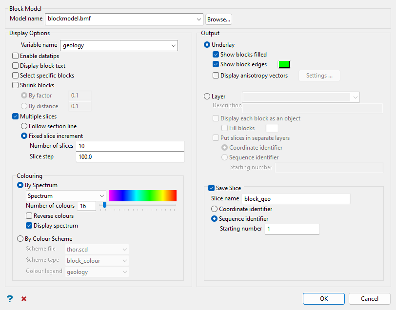
Select the block model using the Model name drop-down list. Click Browse... to select a block model from a location outside the current working directory.
-
Select the information you want to view in the slice in the Display Options section.
-
Select a variable using the Variable name drop-down list.
Note: This is the only mandatory input. All other inputs in this section are optional.
-
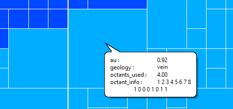
Select Enable datatips if you want to view the block model variable information in the resulting slice. When you hover the cursor over the slice, the appropriate variable information displays.
Important: The Display Datatips check box (under the Graphics section of Vulcan Preferences) needs to be enabled in order to display datatips.
Note: The datatips are only visible when viewing overlays. They are not visibly when viewing slices as layers.
Note: Datatips can be displayed for both filled and non-filled blocks. However, datatips for non-filled blocks will only be visible when in Section view.
 Setting up datatips
If this check box is selected, the Block Model Datatip Variables panel will be displayed once the Dynamic Block Model Details panel has been completed.
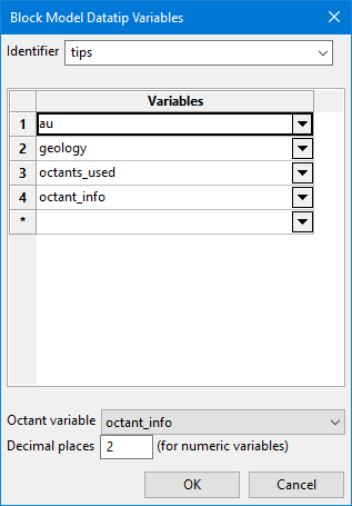
This panel allows you to create and define the template that contains the block model variables that you want to display. The template will be saved to a Block Identifier file
(.bif). This file is named after the name of the project, that is<project_name>.bif.-
Enter a unique name for the panel settings in the space labelled Identfier. The list can then be recalled at a later time by simply selecting the identifier from the drop-down list.
-
Select the variables that you want to display in the datatips. Up to 30 variables can be selected.
-
Select an Octant variable (optional) to hold the information regarding which octants were used in the in the estimation.
ImportantThe variable containing the octant information must be included in the Variables list and be selected as the Octant variable if you want to see it in the datatips. -
Set the number of decimal places you want to view. The number of decimal places enter here will not effect the actual number stored in the model. It is for display purposes only.
Setting up the option to view octant information
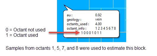
Vulcan stores information regarding whether or not samples from a particular octant were used during estimation. The octants are labelled 1 through 8. If samples from an octant are used during estimation, then the octant is flagged with a 1. If samples from an octant are not used, the octant is flagged with a 0. The variables used to record the number of octants used to estimate a block and record the flag information are stored in variables selected while setting up the estimation parameters.
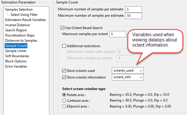
Figure 1 : Screenshot showing panel from Estimation Editor. For information about setting up the estimation variables, see setting up Sample Count .
In the datatips, the octant information is displayed as a small table with the octant number on top and the flag on the bottom.
-
-
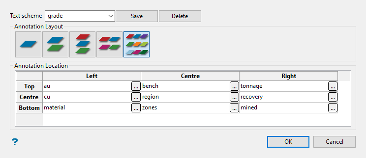
Select Display block text if you want to annotate the block model blocks in the resulting slice.
The text annotations are defined through the Block Text panel, which displays after the Block Model Slice panel is completed.
Setting up block text
-
Type a name for the scheme in the textbox and click
 .
.
-
Select the layout.
There are five format layouts to choose from as shown by the five icons.

As you click on each of the icons, the Annotation Location display window will reflect the change in layout.
Start by clicking on the small
 button in the top left corner. This will cause the Block Model Variable Annotation panel to open.
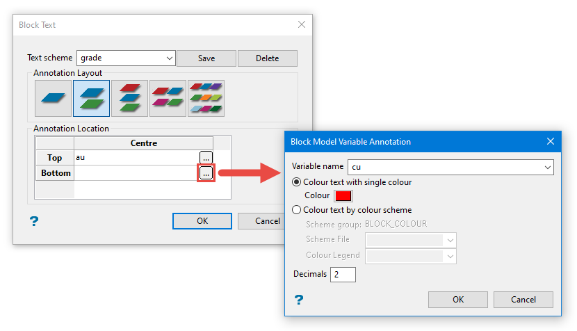
-
-
Select specific blocks allows you to limit the blocks that are displayed in a slice. Once the Block Model Slice panel has been completed, the Block Selection panel will be displayed.
Select the blocks you want to display.
-
Choose Select all blocks to view all blocks.
-
Choose Select specific blocks by if you want to limit which blocks are selected for display. Use the options below as desired to determine which blocks will be selected.
Important: Block selection is cumulative. Therefore, all arguments defined on this panel must be satisfied for a block to be included.
Variable
You will need to specify the variable, as well as a particular value.
Example: If you have a variable called Material in your block model and want to restrict blocks to those where Material equals Ore, select
materialas the variable and enteroreas the value. However, if you require all blocks that do not have this specified value, then enable the Reverse selection check box.Bounding triangulation
This is useful when you want to evaluate reserves in a particular solid triangulation, such as a stope.
Bounding box
If you select this option, you must enter the minimum and maximum coordinates for X, Y, and Z in the block model coordinates (X. Y, Z CENTRE). If the block model origin is set at 0,0,0, then real world coordinates should be entered in the X, Y, and Z minimum and maximum coordinates. If the block model origin is set at real world coordinates, then enter coordinates for the bounding box that are offset a certain distance from the origin. The distance of offset will be determined by the dimensions of your bounding box. It will be the distance to the minimum and the distance to the maximum X, Y and Z from the origin of the block model.
Section thickness
Select this check box to restrict the blocks by a box. The bounding box is defined in Interactive or Coordinate mode. The required mode is selected from the Box Thickness panel, which is displayed once the Block Selection panel has been completed. You may also select the Use block centres check box and use it with this restriction.
Condition
Example: To select blocks where iron has a value greater than 10.0, the condition would be
Fe GT 10.0The maximum length for a condition is 256 alphanumeric characters. Refer to Appendix B of the Core Appendices for a full list of available operators and functions.
Bounding surfaces
Select this to use two limiting surfaces.
Cut and fill surfaces
Select this check box to restrict the blocks to those that fall within two intersecting surfaces. This check box will be disabled when the Bounding surfaces check box is selected.
The required triangulation surfaces are specified through the Cut and Fill Surfaces Selection panel, which is displayed once the Block Selection panel has been completed.
Reverse selection
Select this option to exclude the selected blocks. This option works in combination with the other options on this panel. For example, if you set up Variable to display all blocks that have a gold grade of (-99.0), selecting the Reverse matching option will prevent any block with a gold grade of (-99.0) from being displayed. Or as another example, if you set up a bounding box to limit Z values between 2300m and 5500m, selecting the Reverse matching option will prevent blocks with Z values between those elevations from being displayed and show blocks with all other Z values.
Use block centres
Select this check box if you want to use the full cell evaluation method. If this check box is not selected, then the proportional cell evaluation method will be used instead.
- Full cell evaluation: Include blocks if the block centroid is within the region. The entire block will be included.
- Proportional cell evaluation: Include those blocks that touch the region, and evaluate reserves according to the proportion of the block's volume that lies within the region. Proportional cell evaluation calculates and reports the exact proportion of a block within a solid triangulation. When selecting blocks, all blocks that touch the region are selected.
This is especially important when using options such as Bounding triangulations, Bounding box, or Bounding surfaces.
If a block centroid is not within the boundary area, the block will not be selected.
-
-
Select the Shrink blocks option to shrink the block markers to ensure that the edges do not overlap.
- By factor - This value is entered as a fraction of the block dimensions and must be between 0 and 1.
-
By distance - Enter the distance from the block border.
-
Select the Multiple slices option to create more than one slice.
-
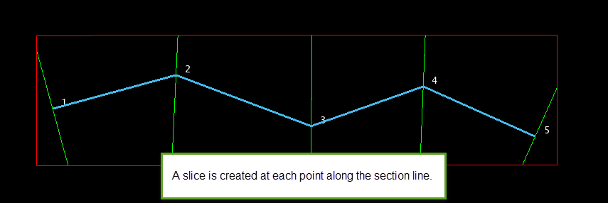
Follow section line - Select this option to create the slices using an existing section line. Once the Block Model Slice panel is complete, you will be required to select the section line from the screen. A slice will be generated at each point along the chosen line.
-
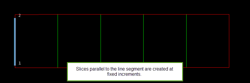
Fixed slice increment - Select this option to create the slices at a fixed increment. You will need to specify the number of slices to create, as well as the slice step.
-
-
Set how the block model slice will be coloured using the options in the Colouring section.
Select the By Spectrum option to colour the slice by spectrum. This means that the selected colour spectrum is stretched over the variable values. If you select the Between two RGB values option from the drop-down list, you will need to nominate two colours to stretch over the variable values. For example, if you select red and blue, then the small values would be red, the middle values purple, and the large values blue. The colour of the middle values is an average of the two chosen colours.
Select the By Colour Scheme option to colour the slice by using a Vulcan colour scheme. A default scheme file and type is entered automatically, these can be altered. Select the file, type, and colour legend from the drop-down lists.
Select the format in which you want to view the slice using the options in the Output section. You can display the resulting slice(s) as an Underlay or as a Layer.
If you select Underlay, the following options are available to you:
Check this box to fill each individual block with colours as designated in the Colouring section.
Select this check box to display the edges of each individual block. You will need to specify a colour for the edges. The colour will be selected from the current colour table.
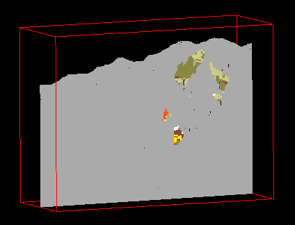
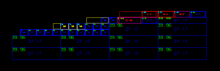
Figure 2 : A Block Model Slice with Filled Blocks
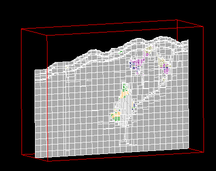
Figure 3 : A Block Model Slice with Filled Blocks and Block Edges Displayed
Select this option and click on  to display the Anisotropy Vectors interface.
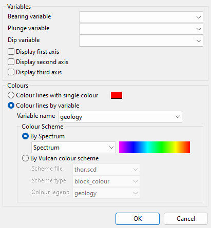
Select the Bearing variable, Plunge variable, and Dip variable from the drop-down lists.
Choose which axes to display by selecting from the Display first axis, Display second axis, and Display third axis options. These axes refer to the major (first), semi-major (second), and minor (third) axes.
Select how to colour the vectors from the following options:
-
Colour lines with single colour: Select this option to colour the vectors all the same colour. Nominate the colour by clicking the adjacent field and choosing from the colour table.
-
Colour lines by variable: Select this option to colour the vectors by variable value.
Select the Variable name from the drop-down list. Next, choose whether to colour By Spectrum or By Vulcan colour scheme:
-
By Spectrum: Select this option to colour by spectrum. This means that the colour spectrum is stretched over the variable values. Use the drop-down list to select the desired spectrum.
If you select the Between two RGB values option, you will need to nominate two colours to stretch over the variable values. For example, if you select red and blue, then the small values would be red, the middle values purple, and the large values blue. The colour of the middle values is an average of the two chosen colours.
-
By Vulcan colour scheme: This option is similar to colour by spectrum in the way it varies by the variable values, but it does so by the customised colour scheme chosen by the user.
Click OK to return to the Block Model Slice panel.
-
If you select Layer, the following options are available to you:
The drop-down list contains the names of all layers found in the currently open design database. If you select an existing layer, then the resulting data will be appended to the nominated layer. If you enter the name of an existing layer that is not currently loaded, then you will need to confirm whether you want to load the layer or replace by overwrite its contents.
To create a new layer, enter the layer name.The layer name:
-
May contain up to forty characters
-
Must begin with an alphanumeric character [0-0] or [a-z].
-
Cannot include spaces.
-
Can include hyphens [ - ], plus signs [ + ], underscores [ _ ], periods/dots [. ].Can include the special characters the are used in the Spanish and Portuguese languages.
Enter a description to further describe the contents of this layer. The description can be up to 80 alphanumeric characters and may include spaces. If a description is not entered, then a default description will be used instead. If the chosen layer already has an assigned description, the description displays when the layer is selected. Existing layer descriptions can be overwritten.
Select this check box to display and save each block in the slice as a separate object. If this check box is not selected, all the blocks in the slice will be saved as a single object. The resulting object(s) will be named BSLICE.
Saving a slice blocks as a single object will allow you to retain the colour information. Saving each block as a separate object, however, will also allow you to apply fill patterns, store datatip information, and generate block text. The block text will be stored as a 3-dimensional text object and will be placed in a different layer ( <layer_name>_TXT ).
Select the Fill block check box and select the adjacent field to select a pattern to fill each block with.
Select this check box to display and save each slice as a separate layer. This option is only available if multiple slices are specified. If this box is not checked, then all slices will be saved as a single layer. If this box is checked, then each slice will be saved to a layer named according to the entry in the Layer field appended with either a Coordinate identifier or a Sequence identifier, as described below:
-
Coordinate identifier: Select this option to append the coordinate identifier to the end of the specified slice layer name. The coordinate identifier value, which is always displayed as a whole number, refers to the coordinate at which the block slice was created.
Example: If
SliceFeis entered as the slice layer name, and one of the resulting slices is created at an RL of534.2, then that slice will be namedSliceFe_534. -
Sequence identifier: Select this option to append the sequence identifier to the end of the specified slice layer name. You will be required to enter a starting number, which will be incremented by 1 for each of the resulting slices.
Example: If
SliceFeis entered as the slice layer name, and you have specified a starting number of5, then the resulting slices will be namedSliceFe_5,SliceFe_6,SliceFe_7, etc.
Click Save slice to setup your saving options.
Select this check box to save the resulting slice(s). The slice name, including the (.bsf) file extension, can contain up to 20 alphanumeric characters in length (spaces are not allowed). The resulting file will be stored in your current working directory.
You can save multiple slices using a Corporate identifier or Sequence identifier.
Select this option to append the coordinate identifier to the end of the specified slice name. The coordinate identifier value, which is always displayed as a whole number, refers to the coordinate at which the block slice was created.
Example: If SliceFe is entered as the slice name, and one of the resulting slices is created at an RL of 534.2, then that slice will be named SliceFe_534.
Select this option to append the sequence identifier to the end of the specified slice name. You will be required to enter a starting number, which will be incremented by 1 for each of the resulting slices.
Example: If SliceFe is entered as the slice name, and you have specified a starting number of 5, then the resulting slices will be name SliceFe_5, SliceFe_6, SliceFe_7, etc.
Click OK on the panel to advance to the Slice Sections interface, where you will define the Dip of your section(s), and choose whether to select a section by line, points, grid coordinate, or by 3 points.

