Attach Viewport
The Attach Viewport option helps you connect a WinTab digitiser tablet to the currently selected window (viewport).
Requirements
Prior to attaching the viewport please ensure that your digitiser is setup correctly. Refer to the Setting Up a Digitiser section for more information. You may want to use the Configure WinTab Context option following the Attach Viewport option.
Instructions
On the Design menu, point to WinTab Digitiser, and then click Attach Viewport.
Define Z
Select one of the following option as your preferred default elevation:
-
Default Z - Select this option to used the default Z value from the graphics driver.
-
Constant Z - Select this option to use a single nominated Z value.
-
User Z - Select this option to use 3-2 nominated Z values.
Enter Control Points
Indicate at least 3 control points to set up the transformation.
In the Enter Control Points section of the panel, there are fields for User X, Y and Z values. Enter the values in the coordinate space of your Vulcan project.
Example: If your Vulcan project coordinates range from 0, 0, 0 to 1000, 1000, 1000, then the points entered as control points must lie between these end points.
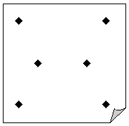
These control points should be arranged in such a manner that no three of the points are co-linear. Although it is possible to create a transformation with three points, the more points you use (to a maximum of six) the more accurate the transformation. Try to place control points so that they cover the extents of your data, as shown in the diagram below:
Note: The User Z values will only be available if you selected the User Z option when defining the default Z method.
Show Transformation Error Report
Select this check box to view a report of the transformation error.
The error report includes the Root Mean Squared (RMS) error value, which gives an indication of the accuracy of the transformation. We recommend that you do check that the error is close to zero prior to digitising objects. Refer to RMS Error for more information.
Click OK.
You are now prompted to digitise the points, using the digitiser, that correspond to the control points. Use the digitiser puck to digitise each point. As each point is entered, you should be prompted to digitise the next point. When all points have been digitised, the process will end and a transformation report displays in the Report Window.
The viewport is now attached to the currently selected window. A cross hair, the digitiser's pointer, displays in the viewport to indicate that input may now come from the digitiser puck.
Any changes to the transformation can be made through the Set Up Transformation option. If the transformation is correct, then you can start design work. Use the Detach Viewport option to detach the digitiser from the currently selected window (viewport).
Important: Using the WinTab Digitiser will force the Custom Cursor on and set the cursor to a fixed size.

