Drillhole Optimiser
Drillhole Optimiser (DHO) is an optimisation tool to assist in the drillhole planning process. DHO optimises drillhole plans given a range of possible drilling budgets and classification criteria to maximise resource conversion at minimal drilling cost. Drilling from both underground pads and surface pads may be considered.
Note: This tool requires a block model of the deposit as well as cost and constraint information on drill rigs and drill pads.
Before starting the Drillhole Optimiser Editor, make sure you have already created a library of available drill rigs and their parameters using the Drill Rigs Library.
Also, load any layer(s) containing the drill pad locations onto the screen. You will need to select these layers as part of the setup process.
Instructions
On the Geology menu, point to Drillhole Optimiser, then click Drillhole Optimiser Editor.
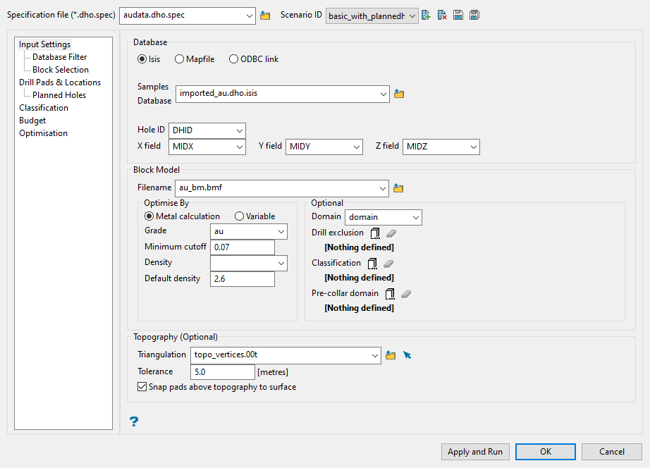
The Drillhole Optimiser opens to the Input Settings pane. Use this pane to enter basic information regarding your specification file, drilling database, block model, and topography triangulation.
Follow these steps:
-
Enter a name for the Specification file, or select one from the drop-down list. The drop-down list displays all files found in the current working directory that have the (
.dho.spec) extension. Click Browse to select a file from another location.TipYou can make changes to an existing DHO specification file, then click the Save As icon to save the edited version under a new name. This allows you to transfer all the parameter settings from the current panel settings to the new file without having to enter everything in again.

-
Enter or select a Scenario ID. To create a new scenario ID, click the New icon, and provide a unique name for the current panel settings. Up to nine separate IDs can be created for each (
.dho.spec) file. -
Establish your database connection.

-
Choose the type of database you are working with by selecting Isis for a composite database in Vulcan, Mapfile for a mapfile with database information, or ODBC link for an internal ODBC.
-
Select the name of the database from the Samples Database drop-down list. This list will show all databases that are stored in your current working directory. If you want to select a database stored somewhere else, click the Browse icon to select one from another location.
-
The Hole ID, X field, Y field, and Z field should automatically populate. However, if the names are different than those shown in the screenshot above you will need to assign the correct fields by using the drop-down lists provided. The X, Y, and Z fields are the coordinates of the sample. Typically these are the mid points, but can be something else. However, they should be consistent.
-
-
Select the block model.

-
Select the block model you want to use from the Filename drop-down list. This list will show all block models that are stored in your current working directory. If you want to select a block model stored somewhere else, click the Browse icon to select one from another location.
-
Select whether you want to optimise by Metal calculation or by Variable.
Metal calculation uses the following criteria:
Metal calculation = Block Volume x Density x GradeIf Grade < cutoff => Metal = 0If Density <= 0 => Metal = Block Volume x Default density x GradeBeing able to optimise by Variable adds flexibility.
You could use recoverable metal, or multiply the grade variable by a mine schedule factor to put higher priority on areas to be mined in the near future.
Another option could be to multiply
grade * average distance to the nearest hole. This would cause the optimiser to target high risk/return areas where the grades are high, but the distance between drillholes are greater.-
If you choose to optimise by Metal calculation, select the variable containing the grade obtained from the block model from the Grade drop-down list. Then enter a Minimum cutoff value in the space provided. The optimiser will target model blocks at or above this cutoff. Also select the block model variable used for Density. If a density variable is not specified, the value considered will be the default density. If the default value for density if it is not defined by a variable, then you will need to enter a value in the space labelled Default density.
Note: Providing the Density variable is mandatory if Default density is not specified. The units shown in the DHO panels are the same as those defined in the DG1 specification file.
-
If you choose to optimise by Variable, select the applicable variable from the drop-down list, which contains existing variables in the nominated block model. Then enter a Minimum cutoff value in the space provided. The optimiser will target model blocks at or above this variable cutoff value.
-
-
-
Set up any options to limit where DHO will allow drillholes to be considered by using the filters in the Optional section. These are all optional and not required. The options include:
 Domain
This will be a block model variable that represents a domain category consisting of either integer or text values. It is used for classification and geologic anisotropy.
After you select a domain variable, use the table on the Classification pane to input the details. (See Classification below.)
 Drill exclusion
This defines areas not to drill. A variable in the model could be coded with voids, or underground development that should be avoided. It accepts categorical and continuous variables.
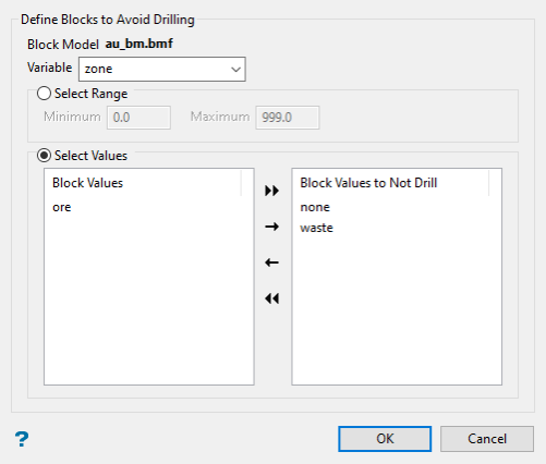
Select the Variable from the drop-down list at the top of the panel.
If the variable holds continuous values (such as assay values), then you will need to select a minimum and maximum value in the space provided labelled Select Range.
If the variable holds discrete values (such as geologic zones), then you will need to select the values you want to use in the Select Values section.
To move list items from one side to another, double-click on the item, or highlight the item(s), then click one of the icons in the middle.

Move all items to right side. 
Move selected items to right side. 
Move selected items to left side. 
Move all items to left side. Note: The section labelled Select Values will be disabled automatically when you are using a variable populated with continuous values.
 Classification
This overrides the DHO generated classification with the actual classification in the block model. Use this to specify what categories to make available for targeting. For example, if you want to drill Inferred blocks and avoid drilling Measured and Indicated, then select Inferred by moving it to the box on the right.
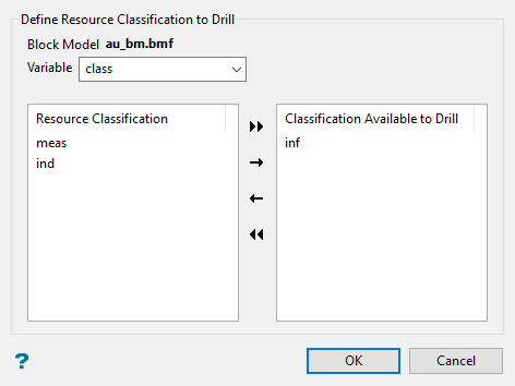
To move list items from one side to another, double-click on the item, or highlight the item(s), then click one of the icons in the middle.

Move all items to right side. 
Move selected items to right side. 
Move selected items to left side. 
Move all items to left side.  Pre-collar domain
Blocks can indicate if they can be drilled as pre-collar or not. A new panel will be opened to select an integer or name type variable in which you can select values to use as pre-collar.
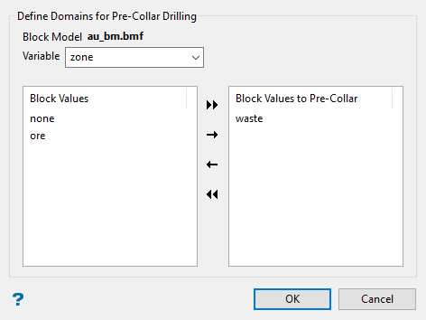
To move list items from one side to another, double-click on the item, or highlight the item(s), then click one of the icons in the middle.

Move all items to right side. 
Move selected items to right side. 
Move selected items to left side. 
Move all items to left side.
-
Define the topography (optional).
-
Select the topographic surface you want to use from the Triangulation drop-down list.

-
Enter the distance from the collar to the topographic surface in the Tolerance field, within which intersections are to be ignored.
Collars above the topography will be adjusted down to topographic surface.
Collars below the topography are assumed to be underground based.
The distance tolerance will act as a buffer to prevent holes from being optimised above the topographic surface.
-
Select the Snap pads above topography to surface checkbox if you want the points representing the drill to snap to your surface triangulation.
-
Database Filter
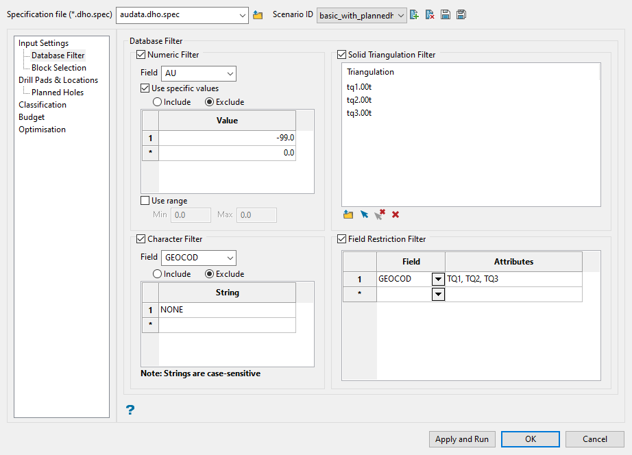
Use this pane to filter your sample data by setting restrictions on samples values, triangulations used, character values within database fields, and field attributes. You can use any combination of the four filters, or not use any at all. This section is optional.
Follow these steps for the desired filters:
-
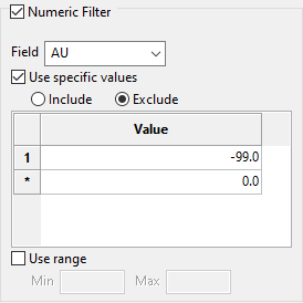
Select the Numeric Filter checkbox to apply numeric restrictions to any field you select from the Field drop-down list. You can use specific values, a range of values, or both.
Note: Only numeric fields will be shown in the drop-down list.
-
Select Use specific values to include or exclude whatever values you list in the Value column in the table.
-
Select Use range to specify a range of values to include with the Min and Max fields.
The range below is evaluated as
0.001 ≤ VALUE < 99999.0.
-
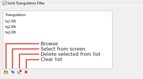
Select the Solid Triangulation Filter checkbox to limit the data by triangulation.
-
Select the triangulations that you want to limit data by with either the Browse of Screen Pick options.
-
Click the Screen Pick icon to select from loaded triangulations in the Vulcan workspace.
-
Click the Browse icon to display the following panel. From here you can select your triangulations. All triangulations found in the current working directory will be listed in the selection panel.
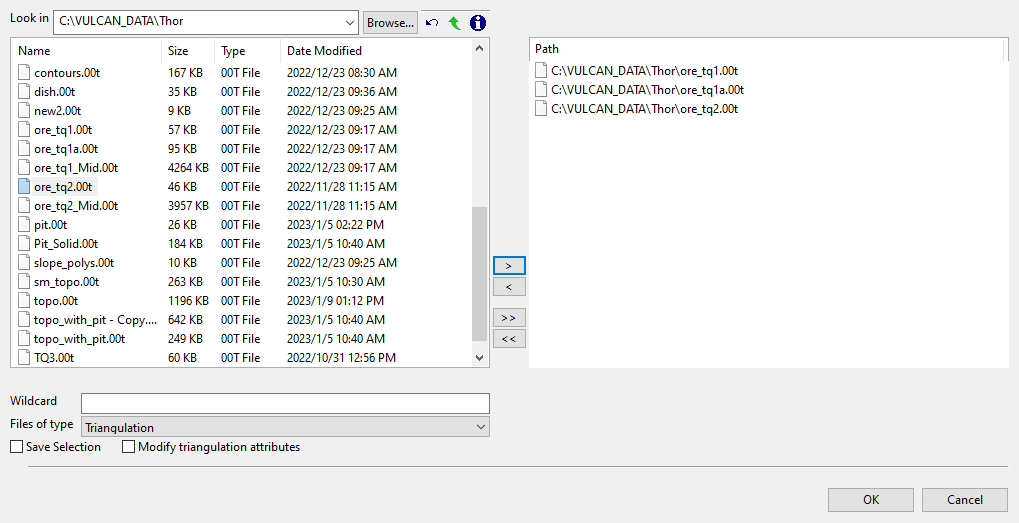
If the list does not contain your desired triangulation, click the Browse... button to search for any triangulation not found in your current working directory.
Click on the name of the file(s) you want to select. Use the
 icons to go to the last folder visited, go up one level, or change the way details are viewed in the window.
To highlight multiple files that are adjacent to each other in the list, hold down the Shift key and click the first and last file names in that section of the list.
To highlight multiple non-adjacent files, hold down the CTRL key while you click the file names.
Move the items to the selection list on the right side of the panel.
- Click the
 button to move the highlighted items to the selection list on the right.
 - Click the
 button to remove the highlighted items from the selection list on the right.
 - Click the
 button to move all items to the selection list on the right.
 - Click the
 button to remove all items from the selection list on the right.
Wildcard characters can be used to limit what appears on the list. Use an * for multiple characters or a % to replace a single character.
- Click the
-
-
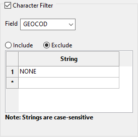
Select the Character Filter checkbox to limit the data by a character string found in the selected database field.
-
Select the database field from the Field drop-down list. Only character fields will be listed.
-
Select whether to Include or Exclude the text string.
Important: The text strings are case sensitive and must be entered exactly as they will be found in the database.
-
Enter the text string without quotation marks in the String column of the table. You can enter multiple strings.
Example: In the image above, our database is populated with four GEOCOD values: TQ1, TQ2, TQ3, and NONE. We have opted to include all values except those samples which have a value of NONE. Any sample that contains a GEOCOD value of NONE will be excluded from our sample population.
-
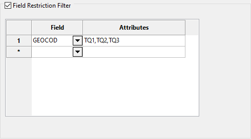
Select the Field Restriction Filter checkbox to limit the samples to those that match certain selection criteria.
-
Select from the Field drop-down lists and define associated criteria in the Attributes column.

Include spaces in the entries in the Attributes column only if spaces are included in the desired field values.
When entering a range, always enter the smallest number specified before the largest number.
Example:
-792&-720since-792is smaller than-720. This range is evaluated as-792.0 ≤ VALUE < -720.0.
Block Selection
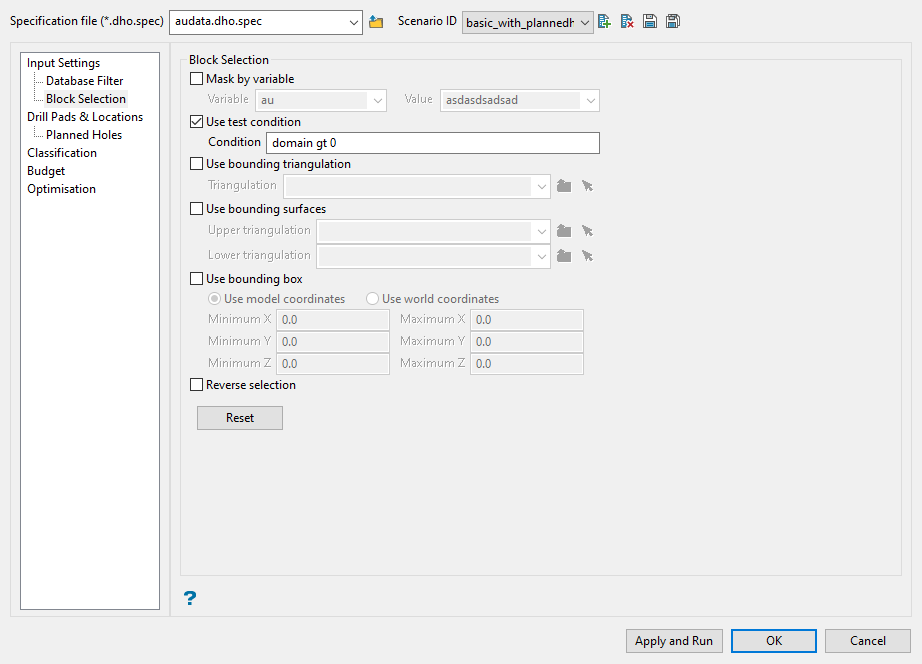
This pane has various options you can use to determine which blocks from your block model will be selected for use.
The available block selection options are described below:
Select this option if you want to restrict the blocks by a chosen variable. You will need to specify a particular value for the variable.
Example: To restrict blocks to those where the Material variable equals Ore, select Material as the variable (from the drop-down list) and enter Ore as the value. However, if you require all blocks that do not have this specified value, then enable the Reverse selection checkbox found at the bottom of the pane. The block model variable may be numeric (for example a grade variable such as Au) or character (for example Geology).
Select this option to use a further constraint upon a numeric variable, for example Fe GT 10.0 (iron value greater than 10.0). The maximum size of a condition is 132 alphanumeric characters. A list of available operators and functions is provided in Appendices B - Operators/Functions.
Select this option to restrict the blocks by a triangulation. You will be required to specify the bounding triangulation.
This option is not applicable to open or 2D triangulations.
Select this option to restrict the blocks by bounding surfaces. You will be required to select the upper (top) and lower (bottom) surface triangulations.
Select this option to restrict the blocks by a box. You will be required to enter the minimum and maximum X, Y, and Z values in either model coordinates or real world coordinates.
Select this option to exclude the selected blocks. This option works in combination with the other options on this pane.
If you set up the Mask by variable section to select all blocks that have a gold grade of -99.0, then selecting Reverse selection will prevent any block with a gold grade of -99.0 from being selected.
As another example, if you set up the Use bounding box section to limit Z values between 2300 m and 5500 m, selecting Reverse selection will prevent blocks with Z values between those elevations from being selected and include blocks with all other Z values.
If you want to reset this pane to the default values for all block model filter options, click the Reset button.
Drill Pads & Location
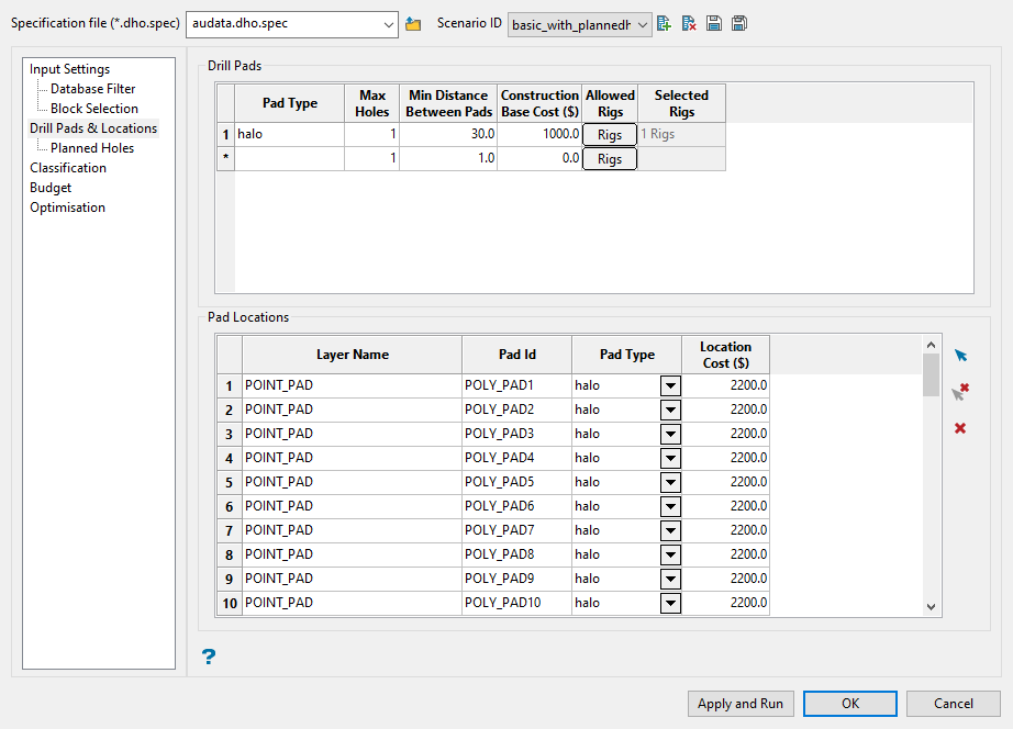
Use this pane to enter information about the different drill pads and their location.
Follow these steps:
-
Enter a name for the drill pad type in the Pad Type column of the Drill Pads table. This field is an alphanumeric ID that is used for referencing this drill pad type.
Note: The drill pad type corresponds to the name of the pad. If this value is changed, the associated values of Pad Type in the Pad Locations table are updated, too.
Pad types could be existing pad, new surface pad construction, existing road, haul road, decline, existing drill bay, etc. Each of these pads will have their own costs based on the amount of prep work required before drilling can commence.
-
Set the maximum number of holes that can be drilled from a single pad in the Max Holes column.
-
Enter the minimum distance that should exist between drill pads of the same pad type into the Min Distance Between Pads column.
-
Enter a base cost of constructing this pad type into the Construction Base Cost ($) column.
-
Click the Rigs button in the Allowed Rigs column. This will open a new window allowing you to select the drill rigs that are permitted and may drill from this pad type.
You can filter the list based on a drill rig name by entering the text into the Rig name pattern field. Use the buttons described below to control the filter.

Sets the filter. 
Removes the filter and clears the list. You can also use the Sorting field drop-down list to select Rig Name or Rig Type to sort by.
To move list items from one side to another, double-click on the item, or highlight the item(s), then click one of the icons in the middle.

Move all items to right side. 
Move selected items to right side. 
Move selected items to left side. 
Move all items to left side. If more than one rig is selected, the program will determine the best drill to use based on the drilling parameters defined in the drill rig library to optimise the given budget.
A summary of the selected rigs (number of rigs) will be shown in the Selected Rigs column. This cell cannot be edited.
-
Populate the Pad Locations table. Do this by clicking the blue arrow on the right side of the table.
Note: You must have the appropriate layer(s) loaded onto the Vulcan workspace prior to clicking the blue selection arrow.
Select the layer(s) holding the pad locations. Allowed elements are points and polylines.
If polygons are selected they are treated as polylines. DHO will find the optimal pad placement along the line trace, not just at inflection points.
When you have selected all the objects, right-click to close the operation and return to the main panel.
The Layer Name column will be populated with the layer in which the object is saved.
The Pad ID column initially gives the object name, but it can be renamed to any string. Pad ID names must be unique for each polyline or point. If duplicates exist, DHO will modify them after asking permission to do so.
The Pad Type column shows drop-down lists of pad types allowed for the locations. The lists are filled with the elements of Allowed Rigs from the Drill Pads table above. If only one pad type is defined, the Pad Type in the Pad Locations table will default to that type.
-
Enter the cost for each pad location in the Location Cost ($) column. This field can be used to apply additional costs/penalties to specific pad types or locations.
If a pad is in a less desirable location, it can be assigned a location cost/penalty to make it a less attractive place to collar from.
An example would be pad locations along an active haul road. This is not a desirable location because it could disrupt mine traffic, but a location cost can be applied to discourage the optimiser from planning holes from there. If holes are still considered optimised at this location it is because it makes the most economic sense to drill from that location regardless of the penalties.
Planned Holes
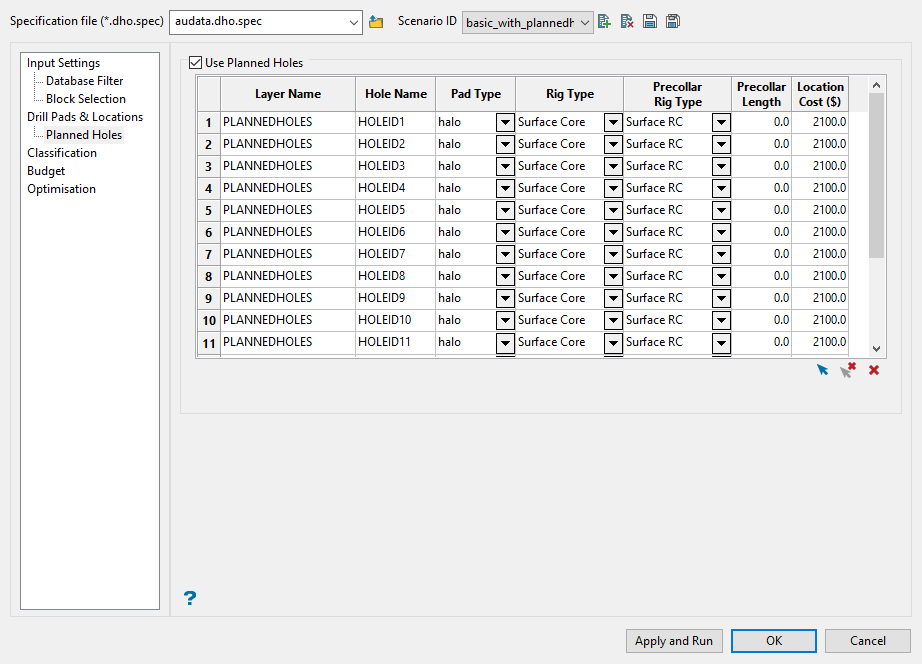
This pane allows you to use existing planned drillholes. This may be useful for checking that specified classification criteria yield results that match external resource results, confirming correct parameterisation of the DHO.
Follow these steps:
-
Make sure you have already created and loaded the layer(s) containing the drillhole polylines onto the screen, then select the Use Planned Holes checkbox and use the blue arrow at the bottom of the table to select the layer(s) from the Vulcan workspace.
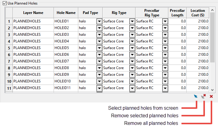
Tip: A quick way to create the holes is to use one of the optimised outputs that already exists. You can also edit an existing layer by extending the length of one of the holes using the CAD tools, or by making a copy of the layer.
Note: Column widths can be adjusted like any standard spreadsheet.
The Layer Name column will automatically be populated with the name of the layer of the selected objects.
The Hole Name column will show the object name for each item in the layer by default. However, you can edit these if you want.
Contents of the Pad Type column is taken from the Pad Type column in the Drill Pads table on the Drill Pads & Locations pane. If there is only one drill pad type listed in the Drill Pads table, then it will be used to populate all the cells in the Pad Type column by default. If there is more than one entry, then you will need to select the pad type using the drop-down lists.
-
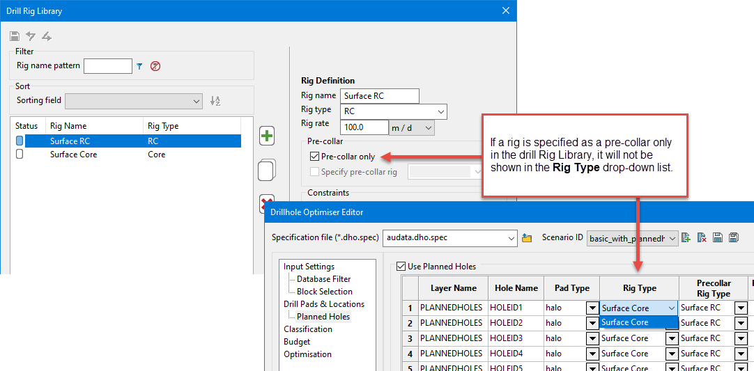
Enter the type of drill rig for each pad in the Rig Type column. This list is generated using the entries from the Drill Rigs Library.
NoteIf a rig has been specified as pre-collar only in the Drill Rig Library, it will not be shown in the Rig Type list.
-
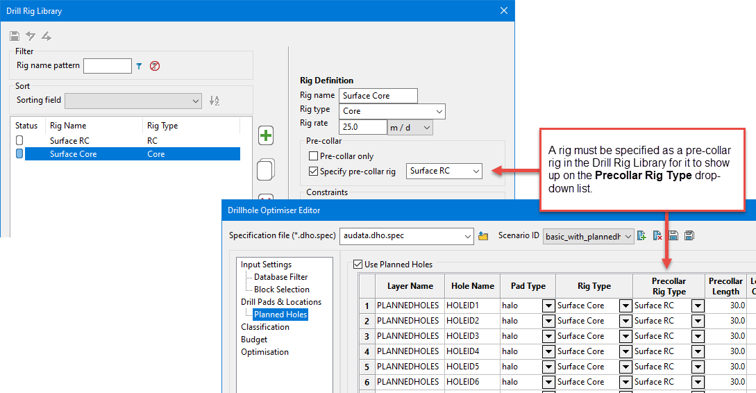
If the planned hole will be drilled using a pre-collar rig, select the rig from the drop-down list in the Precollar Rig Type column.
NoteA rig must be specified as a pre-collar rig in the Drill Rig Library before it will be made available for selection in the DHO Editor.
-
Enter the pre-collar depth into the Precollar Length column.
-
Finally, add the base construction cost for each pad in the Location Cost ($) column.
The total cost for setting up an individual pad is equal to:
(Drill Pads & Construction) Location Cost ($) + (Planned Holes) Location Cost ($)Note: In the case of existing pad locations, total setup cost will frequently be equal to the base
(Planned Holes) Location Cost ($)since(Drill Pads & Construction) Location Cost ($)associated with new earth works will not be applicable.
Classification
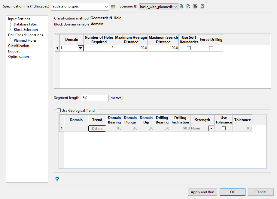
This pane is optional. Use it to set up any classification parameters. The classification is input to the DHO, determining the resource that is classified based on existing drilling, as well as the conversion of resource within the optimisation algorithm from planned holes.
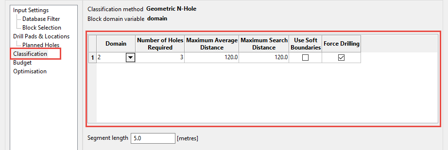
Geometric N-Hole classification defines a block as classified if the average distance between it and the nearest N holes is less than a specified maximum. Best practice is to set the maximum search distance to 1.5 times the maximum average distance. It is also recommended that the minimum number of holes required be 3.
Follow these steps:
-
Select the domain value from the optional Domain drop-down list on the Input Settings pane.
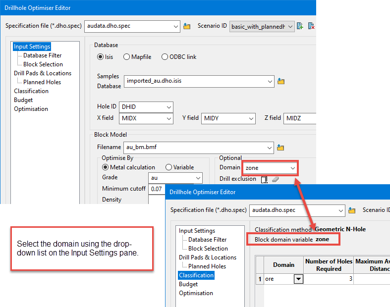
Once selected, the values of the domain variable will populate the drop-down list in the Domain column, then you can select the specific domain you want to use.
-
Enter the number of holes that are required for classification in the Number of Holes Required column. The recommended minimum value is 3.
-
Enter the Maximum Average Distance. A block is classified if the maximum average distance between its model coordinates and the closest N-hole number of holes is less than or equal to the value that is entered into this column.
-
Enter the Maximum Search Distance. Only holes within this isotropic search distance are considered for the N-hole Maximum Average Distance calculation.
Tip: A recommended distance is 1.5 times the maximum average distance.
-
In the Use Soft Boundaries column, indicate whether you want to use soft or hard boundaries when searching for composite data. If soft boundaries are used, then domain coding is ignored when searching for nearby data to test classification.
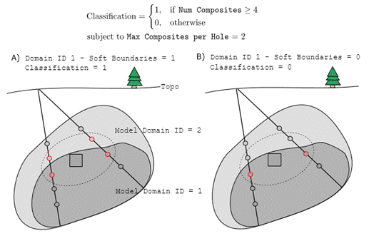
Figure 1 : Schematic of classification with soft (A) and hard (B) boundaries.
-
If you are working with tabular/vein deposits, it may be helpful to enable Force Drilling. If this option is checked, the holes that enter a block in the selected domain must have at least one composite that is not in the domain on both sides. This forces a drillhole to punch through a domain rather than stopping part way through.
-
Enter the length for discretising new drillholes in the Segment length field. This is necessary since all resource classification criteria are based on composite coordinates.
The composite spacing should roughly align with the average composite length in use or the block height. If a compositing strategy different from run-length compositing was used, such as breaking on vein boundaries, then an approximate composite spacing is reasonable. The composite length is required since it is used for all classification variants to code by domain. A smaller composite length will run slower, but only because searching 1M composites takes longer than 100k composites.
-
If you want the holes to be drilled roughly perpendicular to the mineralisation, then enable the option Use Geological Trend.
Customise the angle of drilling by editing the domain bearing, dip, and plunge in the table.
When the Define button is clicked in the Trend column, the following window will be displayed. As changes are made interactively on the screen they will be reflected on this window. Adjustments can be made to any of the parameters except Number of blocks. This allows fine tuning.
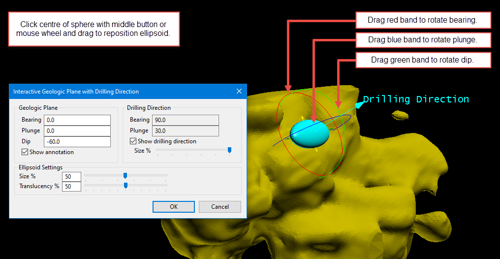
Figure 2 : Make adjustments in the model rotation by hovering the mouse over one of the spherical rings until the cursor changes to a CIRCLE, then hold down the left button of the mouse and drag back and forth to change the rotation. When all adjustments have been made, click OK to save your work and return to the main panel.
Note: While making adjustments in Interactive mode you can still rotate the view on your model just like you would in the normal Vulcan workspace.
-
Set the categorical indicator for the magnitude of anisotropy per domain in the Strength column.
Select from the following types:
None : No anisotropy for this domain, such as an alluvium or glacial till.
Weak : Low anisotropy for this domain, such as a disseminated mineralisation.
Moderate : Moderate anisotropy for this domain, such as a mineralisation with some structural control.
Strong : Strong anisotropy for this domain, such as a narrow vein mineralisation.
Tip: If the optimiser is not producing desirable results, try reducing the strength of anisotropy.
-
If you want to relax the anisotropy trend, click the option Use Tolerance, then set the tolerance angle in the Tolerance column.
This will allow the you to relax the anisotropy trend only if necessary. The tolerance will be applied symmetrically in both sides of the direction. You will be able to set an upper bound on the maximum anisotropy deviation associated with a domain. For planned holes, if one hole intersects a domain with anisotropy constraints enabled, the angle between your preferential drill direction and the angle the drillhole pierces the domain is calculated. If the angle exceeds this value, the hole will not be permitted.
Note: This is a hard constraint parameter and should be used with care. For strong anisotropy, consider setting Tolerance to 30° to more strongly control drilling orientation. For weaker anisotropy, this parameter is likely not useful.
Budget
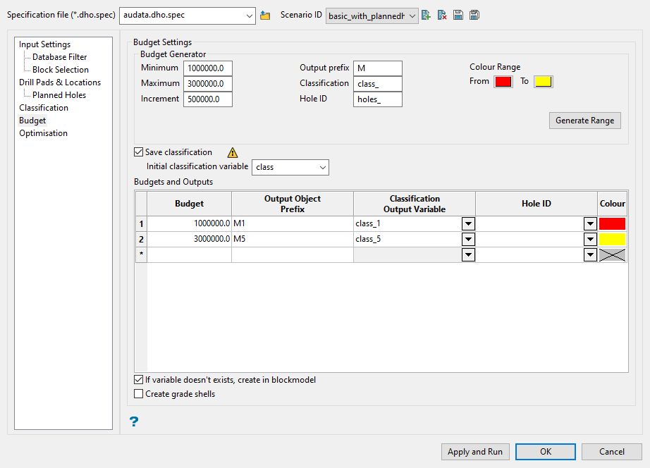
Use this pane to set the budget optimisation thresholds. A simple way to populate the optimisation table is to use the Budget Generator. This will automatically create optimisation thresholds using the parameters you set up.
Follow these steps:
-
Enter the Minimum and Maximum budget constraints, along with the Increment (step) at which you want to run the optimisation.
-
Enter the Output Prefix.
-
Enter a prefix for the Classification output variable.
-
Enter a prefix for the Hole ID variable.
-
Set the Colour Range. This will generate a graded colour range based on the number of output variables created in the table. For more information about the colour table, see File > Colour Table > Colours.
-
Click the Generate Range button to populate the Budgets and Outputs table.
If you would like DHO to save the classifications (both initial and per budget threshold), enable the option to Save classification, then select the variable from the block model where they will be stored by using the Initial Classification Variable drop-down list.
The block model variable saves the result for the initial evaluation as a binary indicator, where:
-
1 means the block is classified
Or
-
0 means not classified
This classification is based on the available drillholes and the classification parameters defined. It is separate from the actual model classification. Care should be taken to NOT select the actual model classification when defining this variable as it will be overwritten.
This evaluation is processed using the composite and block model data provided.
It is recommended that the initial classification be compared to the actual classification to ensure similar blocks are being selected. The closer they match the more relative the conversion/uplift numbers will be.
Important: Caution should be exhibited to not select the model's actual classification variable. These variables will be overwritten during the optimisation. A caution icon appears when variables selected in the budget settings section match variables in the model.
Note
A red label is a cautionary warning that means the variable already exists in the block model. In this example, the variable domain already exists. If we use it to save the Initial classification it will overwrite what was already there. If we type in a new name it would remove the warning. However, when we run it and add the variable to the model it would show up red again because now it exists.
-
-
You have the option to create the variables in the block model if they do not already exist by selecting the If variable doesn't exist, create in blockmodel checkbox.
If this option is enabled, the variables for the initial classification and classification output will be created.
If any of the output classification variables match the optional input variables, then the headers will turn red to indicate there is a conflict. If Apply and Run is pressed the program will not complete the optimisation and comments in the Drillhole Optimiser Window will indicate which variables conflict.
-
Select the Create grade shells checkbox to create a grade shell for the initial classification (blocks classified with the existing drilling) and grade shells for each of the budgets. This is a great way to visualise the impact of the optimised programs.
Note: Grade shells are based on the parent block size. If you have a sub-blocked model with large parent blocks and the optimised blocks are a thin lens, the grade shell may not capture them well.
Optimisation
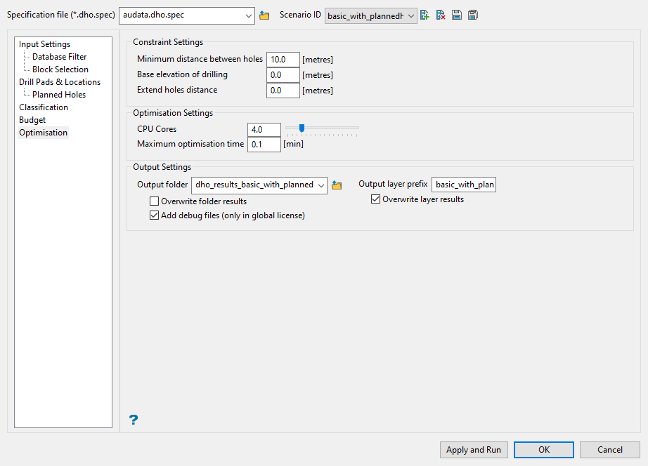
Use this pane to set up the constraint, optimisation, and output settings.
Follow these steps:
-
Enter the minimum distance that should exist between holes in the Minimum distance between holes field.
This distance should be less than the maximum average distance defined in the classification. If the optimiser is not creating holes as desired, this parameter can be reduced to a shorter distance.
-
Enter the minimum elevation the program will optimise to in the Base elevation of drilling field. This could be the base of the model or a level below an open pit where drilling is not desired.
Example: If
600 mis entered, then no composite within an optimised drillhole will be deeper than an elevation of 600 m. -
To specify an extra distance for DHO to extend holes, if possible, enter a distance into the Extend holes distance field. DHO will attempt to extend all planned holes by this length if doing so does not violate a hard constraint (no-drill block, topography, maximum depth, or maximum length that a drill rig can drill).
-
Enter the number of threads to use for parallel optimisation in the CPU Cores field. The time required for conversion is reduced in an approximately linear manner when increasing this number. The minimum value is 1 and the maximum value is the number of CPU cores present in the computer where this application is running.
-
Enter the maximum run time in minutes for optimisation per planned budget into the Maximum optimisation time field, which is approximately respected.
Tip: The recommended run time to start with is 15 minutes. For a more robust optimisation, set it to run overnight. The program uses a number seed. Rerunning the scenario will only produce duplicate results if the optimisation is allowed to run to full completion. Care should be taken when optimisation run times are less than 15 minutes because the results will vary from run to run. This is okay for trial runs, but the results should not be compared with other runs when short run times are selected.
-
Set where your output results will be stored.
-
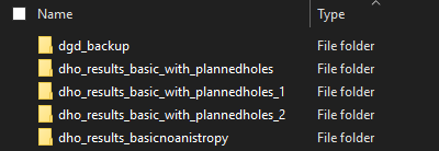
Select a folder from the Output folder drop-down list, or enter a name for a new folder.
Enabling the Overwrite folder results option will allow all the contents of a pre-existing folder to be overwritten.
NoteIf this option is not enabled, then any new results assigned to a folder that already exists will be stored in a folder with the same name that also has a number added to the name as a suffix.
-
Enter a prefix that will be attached to each resulting layer in the Output layer prefix checkbox.
Enabling the Overwrite layer results option will allow layers of the same name from previous runs to be overwritten.
-
Note: An option for those who are working with a global licence is to save the debug files in a separate folder within the output folder. This can be done by enabling the Add debug files (only in global license) checkbox.
Drillhole Optimiser Results
Charts
As part of the results of the DHO, the module delivers two charts, which are displayed after running the optimisation and saved as PNG files in the output directory:
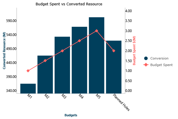
Figure 3 : Conversion Chart, which displays the total of metal converted for each budget spent.
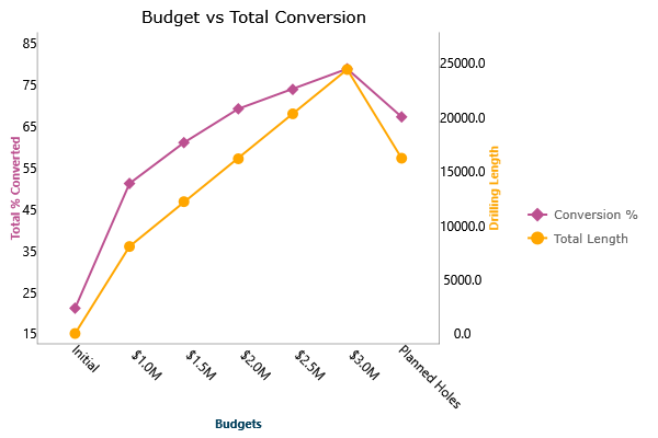
Figure 4 : Total % conversion and footage, which displays the percent of conversion for each budget, plus the drilling length for each one. The percent conversion is based on the total number of blocks available based on the constraints applied.
Planned drillholes draw in Vulcan
For each budget, the optimiser delivers the planned drillholes that can be drilled. Those drillholes are displayed in Vulcan in a specific layer using the defined configuration data to create the layer name.
The following images are examples for 3 different budgets.
-
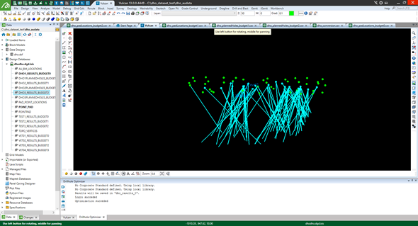
Drillhole results for $1M
-
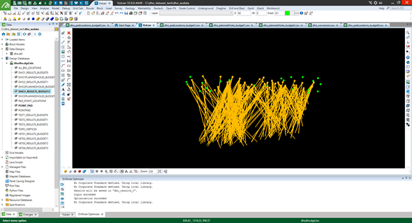
Drillhole results for $2M
-
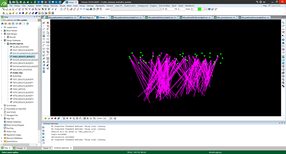
Drillhole results for $3M
CSV with results
The optimiser also provides users with several CSV files as an output. These files are displayed in the Drillhole Optimiser window, indicating the output folder and the path for each file, as shown below. The window also provides a block model summary indicating how many blocks are used in the optimisation.
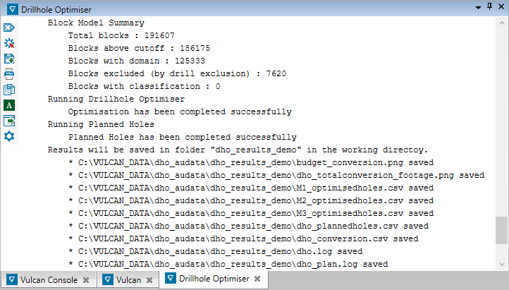
The dho_conversion.csv file lists the budgets and planned holes, if applicable, and the spent budget versus potential conversion for each.
For each budget, a CSV file with the suffix _optimisedholes is created. This file contains the hole ID, collar coordinates, length of hole, azimuth and inclination, the rig, and pad type for each hole in the optimisation. The cost of each hole is shown and the relative uplift or the amount of potential conversion that hole will bring.
If holes are optimised by metal, relative uplift = volume * density * grade will be in the metal units. If another variable is used, it will be volume * variable.
This file also includes the location ID of each drill pad, type, coordinates, and the total cost for that pad. Total cost includes the cost of pad construction and the sum of the drilling costs from that pad. The number of holes drilled from each pad is also shown. This information can be used to develop a basic schedule beginning with the pads from which the most holes can be drilled.
If the Planned Holes pane was used in the DHO, a file named dho_plannedholes.csv is created. This file contains the same fields as the _optimisedholes CSV file that is created for each budget, except the information pertains to the planned holes specified.
