Multi-Label On
Use Multi-Label On to label nominated drillholes with multiple fields from the drillhole database. Each label can be coloured using a colour legend from the drillhole scheme, or through colours specified in the panel.
Note: Change label display settings by using Geology > Drilling > Multi-Label Properties.
Instructions
On the Geology menu, point to Drilling, then click Multi-Label On.
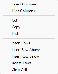
The panel utilises grid controls to manage the grid information, i.e. right-click context menus, that allow you to perform options such as hiding columns, cutting, copying, and pasting cells, and inserting and deleting rows. Right-click in the grid area to display the context menu. Descriptions of the available options are listed below.
-
Use the Select Columns option to choose which grid columns to display in the panel, and optionally save the selection to a template for future use. Alternatively, select cells and click Hide Columns to hide the respective columns directly.
-
Select cells and use the Cut, Copy, and Paste options to duplicate or move cell entries.
-
Select a cell in a row of interest and use the various insert and delete row options to manage the records in the grid.
-
Click Clear Cells to clear the contents of a selection.
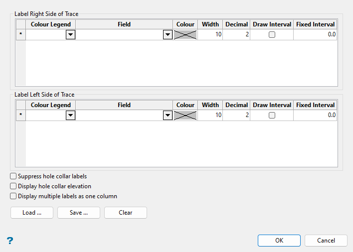
This panel is split into two sections, Label Right Side of Trace and Label Left Side of Trace. The labels for entries in the Label Right Side of Trace section will be displayed to the right of the drillhole trace and the labels for entries in the left section will be displayed on the left.
In the diagram below, the CU and AU (numeric) legends are used to label on the right, and the LITH (alpha) legend to label on the left side of the drillhole.
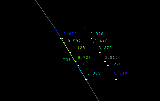
Figure 1 : Multiple Drillhole Labels
The label specifications are stored in a file named <name>.mls in a directory of your choice. We recommend, however, that you store the label specifications in the same location as the drillhole data. This is to avoid potential problems with using label specifications created for one set of data with a different set of data.
Note: Label specifications created in version 3.5x cannot be used in newer versions of Vulcan and vice versa.
It is possible to create the labels using four different methods: Colour Legend column only, Field and Colour columns, Colour Legend and Field columns, and Field column only with a default colour.
The Colour Legend cell contains a drop-down list of all available DRILL colour legends. Select a scheme from this list if you want to label the drillhole(s) using one of these colour schemes.
For example, you might use the CU scheme to label the drillhole(s) with the copper assay values. If you do not select a colour, then the colour of the labels will be derived from the scheme.
You can create schemes through the Analyse > Legend Edit > Legend Editor option.
In the following diagram, the AU and CU schemes were used to label the right side of the trace with the LITH scheme being used to label the left side. A colour was not selected from the available Colour field, a Width of 10 was used, the number of Decimal places was set to 3, and the Draw Intervals option was enabled. The drillhole was displayed on the screen using the AU scheme.

Figure 2 : Scheme Only
The Field cell contains a drop-down list of all of the fields in the open drillhole database. From this list select the field that you want to label on the drillhole(s). From the Colour cell, select the colour for the labels.
If you make selections from the Colour Legend and Field columns, then the drillhole will be labelled with the values from the field, but using the colours from the scheme. Using this method could create labels that are not indicative of the chosen field. Schema are designed to highlight particular qualities and using them to colour fields for which they were not designed could produce misleading or confusing labels.
In the following diagram, the AU scheme and ASSAY:CU field were used to label the right side of the trace, with the LITH scheme being used to label the left. A colour was not selected from the available Colour field, a Width of 10 was used, the number of Decimal places was set to 3, and the Draw Intervals option was enabled. The drillhole was displayed on the screen using the AU scheme.
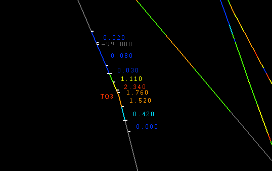
Figure 3 : Schema and Field
If only the Field is selected, then whichever colour is chosen in the Status toolbar will be used.
In the following diagram, a field was selected without a colour in the panel, and the resulting labels were coloured magenta by default based on the current colour selected in the Status toolbar, as shown.
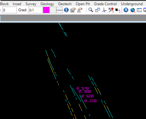
Figure 4 : Field Only
Width
Enter a width for the label column alongside the drillhole trace to set the horizontal spacing between multiple labels. The default value is 10 and entries for this field can range from 1 to 100.
Decimal
Enter the number of decimal places to display for the label. The default value is 2 and entries for this field can range from 0 to 6.
Draw Interval
Select this box if you want to display interval markers along the drillhole trace.
Fixed Interval
This field allows you to specify a fixed depth labelling interval. If a depth is specified, then the drillhole labels will be produced only in increments of this depth.
Note: If the Field being labelled is the FROM or TO field, then the actual depth is labelled rather than a value extracted from the database.
Suppress hole collar labels
Select this box if you do not want to display the drillhole collar labels along the drillhole trace. If this check box is not selected, then the drillhole collar labels will be displayed.
Display hole collar elevation
Select this box if you want to display the drillhole collar elevation.
Display multiple labels as one column
The default (when the option is unchecked) is for the labels to display as columns horizontally.
When this option is checked, multiple labels on a given side of the trace display vertically aligned (stacked).
Load
Use this button if you want to reload previously created label specifications. These specifications are stored within a .mls file. Although it is possible to load specifications from a directory outside of your current working directory, we recommend that you only use specifications that were created for the drillhole data that you are currently using.
Save
Use this button to save the label specifications. You can save the .mls specifications file within any directory, however, we recommend that you save it in the same location as the drillhole data, i.e. in your current working directory.
Clear
Use this button to clear the panel.
Click OK.
The labels are displayed and you will be prompted to select another drillhole for labelling, which if selected will be labelled in the same manner as the original drillhole. Right-click to cancel selecting drillholes. Depending upon your selection method, you might need to cancel several times to exit the option.

