Flag Samples - Triangulation
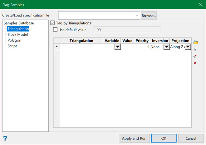
Flag by Triangulations
Select this check box to store a value into a field associated with a sample, according to the solid in which the sample resides.
Use default value
Select this check box to enter a default value. This value will be stored in the nominated variable when a block is not in a selected polygon.
Triangulation
Triangulation files can be added through manually entering the file name, using the drop-down list, browsing data directories, or selecting a loaded triangulation directly from the screen using the controls on the right.
To remove a triangulation, right-click the applicable row and select Delete Rows from the displayed context menu.
Variable
Select the variable in which to place the flag.
Value
Enter the flag value for the triangulation.
Priority
Figure 1 : 3D Triangulation Inversions
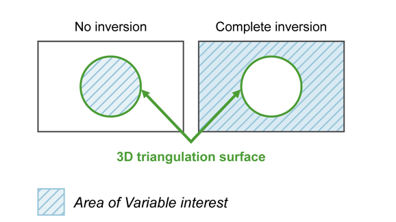
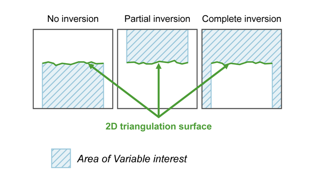
Figure 2 : 2D Triangulation Inversions
Projection
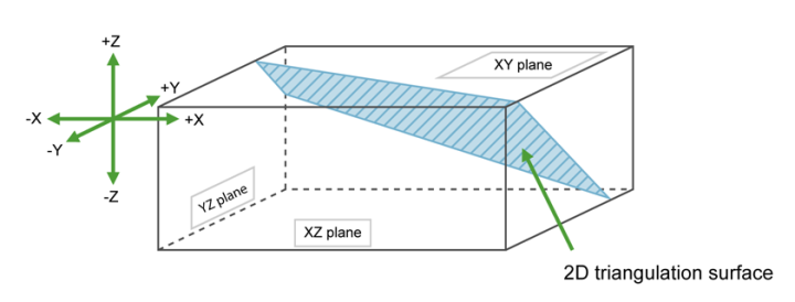
Select the projection axis. This defines the direction for a surface and has no effect when working with solids. This option is used in situations where steeply dipping structures define regions.
Figure 3 : Projection Axes
If None (no inversion) was selected, the negative side of the triangulation is the area of interest.
If Partial or Complete inversion was selected, the positive side of the triangulation is the area of interest.
Figure 4 : Projection along the X Axis
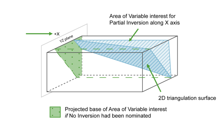
For triangulations (ore bodies) that are steeply dipping, it may be necessary to project along the X or Y axis to ensure the correct inversion is applied.
Figure 5 : Projection along the Y Axis
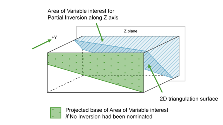
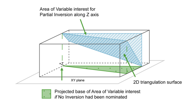
For triangulations (ore bodies) that are near to horizontal (that is lying in the XY plane), project along the Z axis. The area of interest is then either below the triangulation if None (no inversion) was selected, or above it if Partial or Complete was selected.
Figure 6 : Projection along the Z Axis
Note: The following order will be used when one or more methods have been selected:
1. By Triangulation
2. By Block Model
3. By Polygon
4. By Script
Related Topics

