Tutorial - Polygon Flag
This tutorial provides step-by-step instructions on how to use the polygon flag feature, including how to open the data in Vulcan, how to select your flagging options, and how to view your flagged block model.
The Polygon Flag option to store a value in a block model variable according to the polygon in which that block resides.
Opening Your Data File in Vulcan
Instructions
The first step is to prepare and open your data file in Vulcan.
-
Create a new folder on your local drive. For this tutorial, we will use a folder called Polygon_Flag_Data_File
-
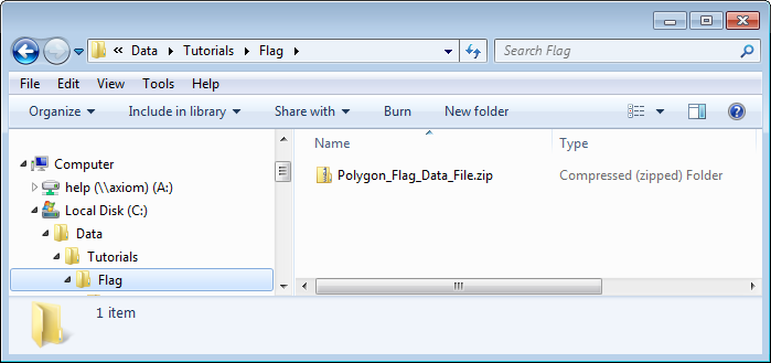
Download the sample tutorial by clicking the following link and saving the.zip file on your local drive: Download Polygon_Flag_Data_File.zip
-
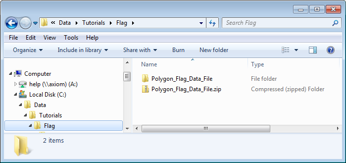
Extract the data from the.zip file to C:\Data\Tutorials\Flag\Polygon_Flag_Data_File that contains the files required for this tutorial.
-
Open the Vulcan application using the unzipped files using one of the following methods.
To open Vulcan directly and browse to the data file folder:
- Double-click the Vulcan button on your desktop to open Vulcan.
- Browse to your data folder by clicking Browse in the Work Area Section of the Vulcan Launcher window.
- Select your data folder C:\Data\Tutorials\Flag\Polygon_Flag_Data_File and click OK.
- Click Vulcan.
- Select tutorial.dgd.isis in the Design File drop-down menu.
To open Vulcan by clicking and dragging the data file:
- Click on your C:\Data\Tutorials\Flag\Polygon_Flag_Data_File folder that you created in Step 3 and drag it on top of the Vulcan button in your desktop to launch Vulcan with the data from the folder.
- Click Vulcan.
- Select tutorial.dgd.isis in the Design File drop-down menu.
Result:
The tutorial data that you extracted from Polygon_Flag_Data_File.zip is now loaded.
Next step:
You can now load the layer with the polygon and begin the flagging process.
Loading the Layer with the Polygon
Instructions
Now that you have opened your data file, the next step is to load the layer containing the polygon and start the flagging process.
For this example, the block model tutorial.bmf will be used. You will flag the variable named bearing with the value of 1 (one) for blocks inside the polygons and with a value of 0 (zero) for blocks outside the polygons.
-
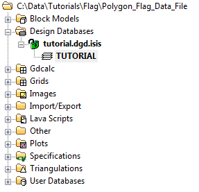
Open the layer named TUTORIAL using the Windows Explorer pane on the left side of the screen.
- Double-click Design Databases.
- Double-click tutorial.dgd.isis to open the design database.
- Double-click TUTORIAL to load the layer.
-
If necessary, click the Zoom Data Extents button (
 ) on the Graphics toolbar on the right side of the screen. This will re-centre the layer in the centre of the screen and zoom to fit the entire object on the screen.
 -
Inspect the data. The polygons should roughly define a known geometric shape.
Result:
The polygon layer is now loaded and ready for flagging.
Next step:
Now you are ready to flag your block model. You can flag your block model using a single set of sections, or you can flag your block model using the ellipsoid method.
Flag Your Block Model Using Polygon Flag - Flag Using a Single Set of Sections
Instructions
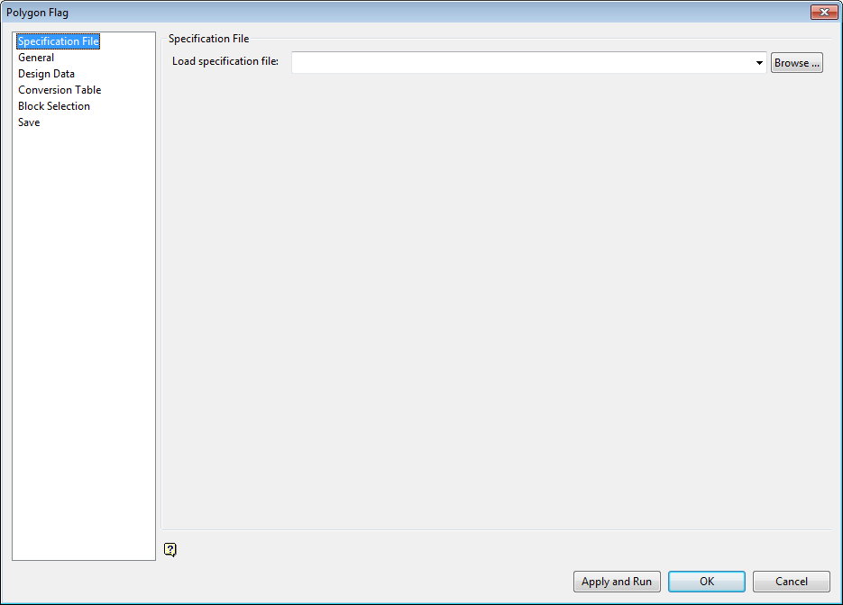
The next step is to define the parameters for the polygon flag using the Polygon Flag panel.
There are six branches on each panel that are listed on the left side of the panel. Each panel has different parameters that must be set in order to flag your polygon. The screenshots below indicate how the screens should be completed for the example in this tutorial.
Note: You can also use the polygon flag feature to flag using the ellipsoid method as described in the next section of the tutorial.
-
Select Block > Manipulation > Polygon Flag to display the Polygon Flag panel.
-
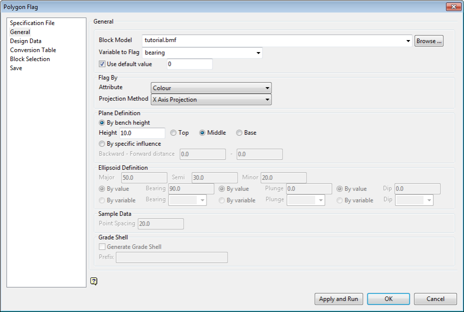
Click the General branch on the left side of the Polygon Flag panel.
-
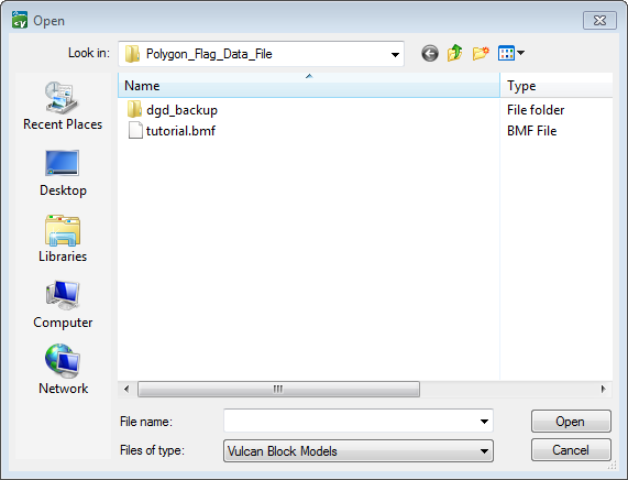
Select tutorial.bmf from the Block Model list.
-
Select bearing from the Variable to Flag list.
-
Select the Use default value check box and enter 0 (zero) in the box beside it. This will flag those blocks that are outside the polygon with the value that you specify in the box (zero, in this example) in addition to flagging the blocks that are inside the polygon.
-
Select Colour from the Attribute list.
-
Select X Axis Projection from the Projection Method list.
-
Select By bench height in the Plane Definition section, and enter 10.0 as the height and Middle as the position.
-
-
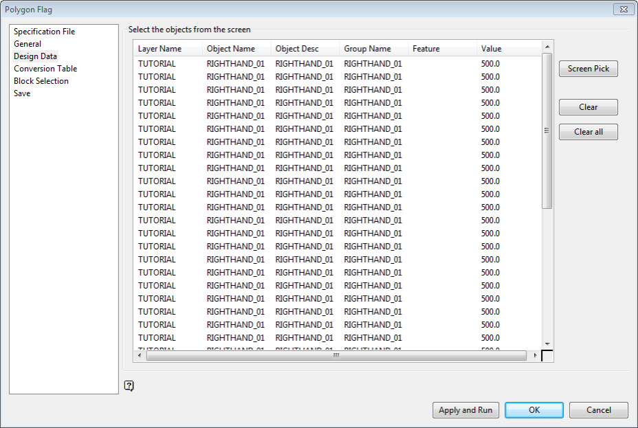
Click the Design Data branch on the left side of the Polygon Flag panel.
-
Click Screen Pick.
-
Click Layer on the Select By menu.
-
Click on the layer.
-
Click Layer="TUTORIAL" in the Confirm menu that displays.
-
Click Cancel to return to the Polygon Flag panel.
-
-
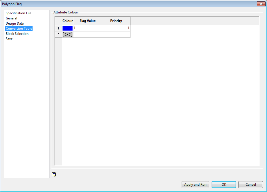
Click the Conversion Table branch on the left side of the Polygon Flag panel.
-
Enter 1 (one) as the Flag Value.
-
The Priority defaults to 1 (one) since there is only one polygon in this example.
-
-
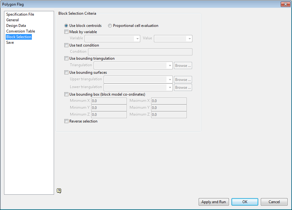
Click the Block Selection branch on the left side of the Polygon Flag panel.
-
Select Use block centroids.
-
In this case, leave all block selection criteria unchecked so that all blocks are selected.
-
-
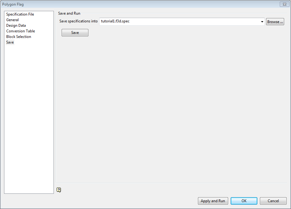
Click the Save branch on the left side of the Polygon Flag panel.
-
Enter tutorial1.f3d.spec in the Save specifications into list.
-
Click Save.
-
-
Click Apply and Run to generate the flagged polygon.
Result:
The polygon is flagged using the parameters you have established on the Polygon Flag panel.
Next step:
You can now view your results in the block model.
F lag Your Block Model Using Polygon Flag - Flag Using the Ellipsoid Method
Instructions
The next step is to define the parameters for the polygon flag using the Polygon Flag panel.
There are six branches on each panel that are listed on the left side of the panel. Each panel has different parameters that must be set in order to flag your polygon. The screenshots below indicate how the screens should be completed for the example in this tutorial.
Note: You can also use the polygon flag feature to flag using a single set of sections as described in the previous section of the tutorial.
-
Select Block > Manipulation > Polygon Flag to display the Polygon Flag panel.
-
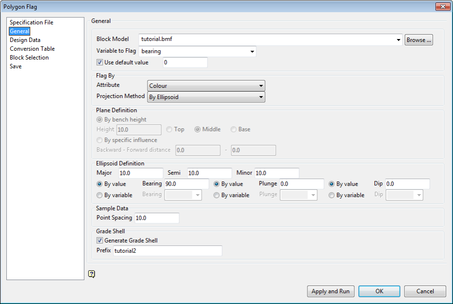
Click the General branch on the left side of the Polygon Flag panel.
-
Select tutorial.bmf from the Block Model list.
-
Select bearing from the Variable to Flag list.
-
Select the Use default value check box and enter 0 (zero) in the box beside it. This will flag those blocks that are outside the polygon with the value that you specify in the box (zero, in this example) in addition to flagging the blocks that are inside the polygon.
-
Select Colour from the Attribute list.
-
Select By Ellipsoid from the Projection Method list.
-
Enter 10.0 in the Major, Semi, and Minor boxes.
-
Select By value next to the Bearing, Plunge, and Dip options.
-
Enter 90.0 in the Bearing box.
-
Enter 0.0 in the Plunge box.
-
Enter 0.0 in the Dip box.
-
Enter 10.0 in the Point Spacing box.
-
Select the Generate Grade Shell check box.
-
Enter tutorial2 in the Prefix box.
-
-
-
Click the Design Data branch on the left side of the Polygon Flag panel.
-
Click Screen Pick.
-
Click Layer on the Select By menu.
-
Click on the layer.
-
Click Layer="TUTORIAL" in the Confirm menu that displays.
-
Click Cancel to return to the Polygon Flag panel.
-
-
Click the Conversion Table branch on the left side of the Polygon Flag panel.
-
Enter 1 (one) as the Flag Value.
-
The Priority defaults to 1 (one) since there is only one polygon in this example.
-
-
Click the Block Selection branch on the left side of the Polygon Flag panel.
-
In this case, leave all block selection criteria unchecked so that all blocks are selected.
-
-
Click the Save branch on the left side of the Polygon Flag panel.
-
Enter tutorial1.f3d.spec in the Save specifications into list.
-
Click Save.
-
-
Click Apply and Run.
Result:
The polygon is flagged using the parameters you have established on the Polygon Flag panel.
Next step:
You can now view your results in the block model.
Viewing Your Results
Instructions
You can now view your results in the flagged block model.
Your blocks are flagged with 1 (one) inside the polygons and 0 (zero) outside the polygons. You specified an influence of 10, which is the distance between sections in this example.
-
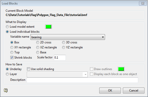
Select Block > Viewing > Blocks to select a block model file.
-
Select the tutorial.bmf block model file from the C:\Data\Tutorials\Flag\Polygon_Flag_Data_File folder.
-
Select Load individual blocks.
-
Select bearing from the Variable name list.
-
Select Box as the block representation method.
-
Select the Shrink blocks check box to shrink the block markers to ensure that the edges do not overlap.
-
Enter a Scale factor of 0.1 to indicate how much to shrink the blocks.
-
Select Underlay in the How to Save section.
-
Click OK.
-
-
Select Select specific blocks by:
- Select Variable.
- Select bearing from the drop-down list.
- Enter 1 (one) as the Value.
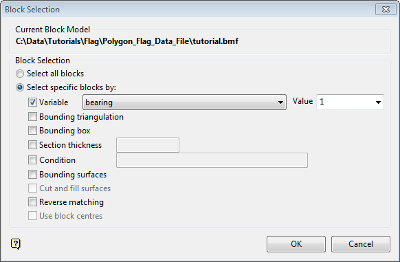
- Click OK.
Result:
The blocks are displayed. The blocks displayed should match the polygons used for flagging on the screen.
Related topics

