Smart Snap
 Smart Snap mode can only be used with the following options:
- Design > Create > Point
- Design > Create > Line
- Design > Create > Polygon
- Design > Create > Polygon Textured
You can use the keyboard shortcut to switch to Smart Snap by pressing the O key when in point insertion mode,
To access the Smart Snap Properties panel, right-click on the Smart Snap icon in the Digitise toolbar.
Smart Snap Properties panel
The Smart Snap Properties panel consists of the following tabbed sections:
The Smart Snap Properties panel can be docked by dragging the panel to the edges of the Primary Window (a preview of its docked position will be displayed) or through double-clicking the panel's title bar.
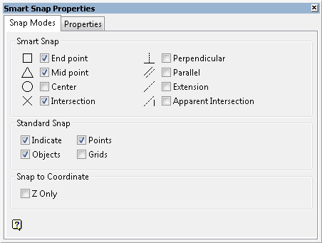
Snap Modes tab
Smart Snap
This section allows you to select the type of points to create, as well as their position, when digitising or snapping to objects in Smart Snap mode. Use the C key to centre you view on the last digitised point.
The highlight and overlay colours, which are assigned through the Graphics : Colours section of the Tools > Preferences option, will be used to colour the cursor symbols as well as the temporary point.
End point
Select this option if you want to locate the end point of a nominated object, such as a line or arc.
Mid point
Select this option if you want to locate the exact middle of a nominated object, such as a line or arc. The chosen object must have a defined start point and end point.
Centre
Select this option if you want to locate the exact centre of a nominated object, such as a circle, ellipse or arc.
Intersection
Select this option if you want to locate where loaded objects physically intersect in 3-dimensional space. Smart Snap will automatically snap to the design object with the greater Z-value. To snap to the design object with the lower Z-value, simply press the Space key to cycle between the available intersection points.
Perpendicular point
Select this option if you want to snap to a point that forms a 90° angle between the existing line segment and a new line. A perpendicular mouse pointer gives hint about the point where the new line forms 90° with the existing line.
Perpendicular line
Select this option if you want to draw objects that are at a 90° angle to another loaded object.
Parallel
Select this option if you want to draw objects that are parallel to another loaded object. To draw a parallel line, you will first need to indicate the new line's starting point before positioning the mouse cursor over the reference object.
Extension
Select this option if you want to draw objects along a proposed extension of an existing line.
Apparent Intersection
Select this option if you want to draw objects at locations where they appear to intersect in 3-dimensional space, i.e. the objects used do not actually have to physically intersect. Like the Parallel option, you will need to indicate the starting point before positioning the mouse cursor over the reference object.
Standard Snap
This section allows you to mimic Vulcan's existing snapping modes, i.e.  Indicate mode,
  Snap to Points mode etc., when using Smart Snap mode. One or more of the available checkboxes can be ticked, however, the Indicate checkbox must be ticked in order to use the Smart Snap functionality. If the Indicate checkbox is not ticked, then all checkboxes under the Snap Modes tab will be disabled, i.e. greyed out.
If all of the available snapping checkboxes have been ticked, then Snap to Points mode ( Points ) will take precedence over the other snapping modes. If a point within the defined snap tolerance cannot be located, Smart Snap will use  Snap to Objects mode ( Objects ) before moving to
  Snap to Grids mode ( Grids ) and Indicate mode ( Indicate ).
Press the Shift key if you want to display the proposed snapping position. Once the Shift key has been pressed, the mouse cursor will snap to the nearest object using the chosen snapping options. Use the N key if you want to cycle through the different snap modes within Vulcan VH_VERSION_VH, i.e. Indicate mode, Snap to Points mode etc.
Snap to Coordinate
To enable snapping to the closest point based on its Z-coordinate value, tick the Z Only box. If this box is greyed out, select Indicate and one or more Standard Snap features. Ticking the Z Only box disables the Perpendicular, Parallel, Extension, and Apparent Intersection drawing options in this tab.
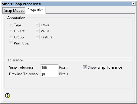
Properties tab
Annotation
This section allows you to display object information, such as the object type, layer name, object value, etc. via Vulcan's existing datatip functionality. One or more of the available checkboxes can be ticked (as shown in the following diagram). The selected information will be displayed when the mouse cursor is positioned over an object.
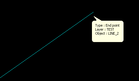
Figure 1: Datatip Information
The Display Datatips checkbox (under the Graphics section of the Tools > Preferences option) needs to be ticked in order to display the information through datatips.
Tolerance
The tolerance values specified through this section of the Smart Snap Properties panel refers to the number of pixels away from an object the Smart Snap mouse cursor needs to be before snapping and digitising takes effect. This defined boundary is known as the "selection zone".
Snap Tolerance
Type the required size of the snapping selection zone.
Drawing Tolerance
Type the required size of the selection zone used for the Perpendicular, Parallel, Extension, and Apparent Intersection drawing options located in the Snap Modes tab.
Show Snap Tolerance
Select this option to display the snap tolerance on the mouse cursor.
Related topics


