Edit Holes
Edit Hole Attributes
Use the Edit Holes option to edit the attributes of existing Drill and Blast holes.
Instructions
On the Drill and Blast menu, point to Edit, then click Edit Holes.
The Select hole(s) by dialog box is then displayed.
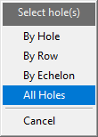
Using the displayed dialog box, nominate a method by which to select the holes. You have the choice of selecting by hole, by row or by echelon. Use the All Holes option to edit all of the holes from a particular blast.
Once chosen, the following panel displays.
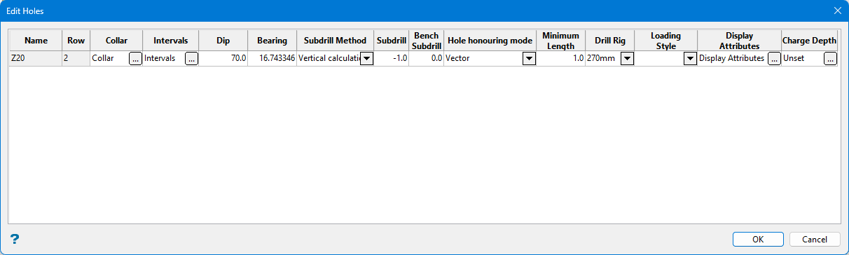
Name
This displays the name of the blast hole that has been selected. This field cannot be edited because it is a display field only.
Row
This displays the row in which the blast hole is located. This field cannot be edited because it is a display field only.
Collar
Click the  icon to display the Hole Collar panel.
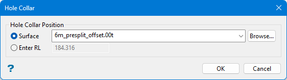
Hole Collar Position
-
Surface - Select the surface triangulation from the drop-down if the surface is stored in the current working directory, or click Browse to search for it if it is stored in another directory.
-
Enter RL - Enter the elevation level.
Intervals
-
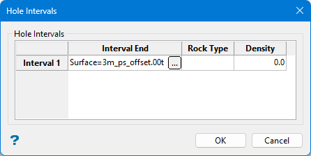
Interval End - Click the
icon to display the Define end of interval panel.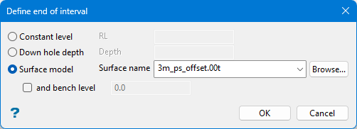
-
Constant level - Enter an elevation level.
-
Down hole depth - Enter a hole depth.
-
Surface model - Select a surface triangulation from the drop-down if the surface is stored in the current working directory, or click Browse to search for one that is stored in another directory.
-
and bench level - Select this option if the hole is limited to a certain bench level, then enter the bench level.
-
-
Rock Type - Enter a rock type if you want to use it as a limiting boundary to the interval length.
-
Density - Enter a density if you want to use it as a limiting boundary to the interval length.
Note: All conditions must be met for the interval to be set.
Dip
Enter the dip angle of the blast hole.
Bearing
Enter the bearing of the blast hole.
Subdrill Method
Select the subdrill method from the drop-down list.
-
Vertical calculation - Target horizon minus subdrill depth (vertically).
-
Vertical surface intercept - Target horizon adjusted vertically by subdrill depth.
-
Along hole vector calculation - Target horizon minus subdrill depth (along hole vector).
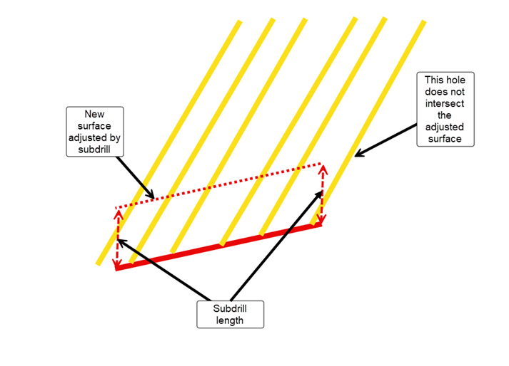
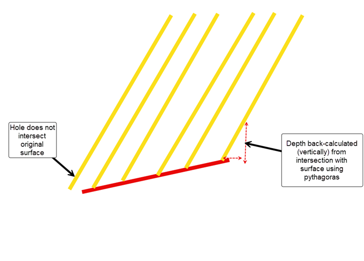
There are different methods of calculating the standoff, each of which are valid depending on the angle in which you have your blast holes set up. In some circumstances, there may be issues with the surface not intersecting the holes:
-
Scenario One - If you move the surface vertically by the subdrill amount and then determine the intercept, it's possible that a hole which originally intersected the original surface will no longer intersect the surface in the surface's adjusted position. For example, when using a negative subdrill (i.e. standoff).
-
Scenario Two - If you calculate the intersection from the original surface, it is possible that the hole's vector will not intersect the original triangulation.
Subdrill
Enter the depth below the target floor or grade elevation of your bench.
Hole honouring mode
Use the drop-down list to select either Vector or Location mode.
-
Vector - The bearing and dip vectors are maintained, and the position can change. In this case, the processing is always forced as if the hole were built from top to bottom (in other words, the collar's position dictates the process). If a subdrill is added, it sticks to the toe, and the toe changes position to keep the vector fixed.
-
Location - The position is maintained (depending on whether the hole is drilled from top to bottom or bottom to top), although the bearing/dip vector can change.
Minimum Length
This is the minimum length for an interval.
Drill Rig
Select the drill rig from teh drop-down list. This list is generated from the Drill Rig Library.
Loading Style
Select the loading style from the drop-down list.
Display Attributes
Click the icon to display the Display Attributes panel.
Note: Refer to Drill and Blast > Edit > Edit Display Attributes for information.
Charge Depth
Click the icon to display the Design Charge Depth Intercept panel.
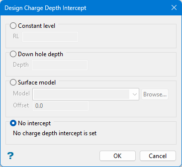
Select one of the following options:
-
Constant level - Enter the elevation depth.
-
Down hole depth - Enter the down-hole distance from the collar.
-
Surface model - Select the surface triangulation from the drop-down list.
-
No intercept - Default setting of no depth intercept.
When you have completed the edits in the table, click OK. The changes will be applied and the blast updated.
It is also possible to edit specific hole attributes using the Vulcan context menu. Simply highlight the desired hole(s) and select the appropriate option from the displayed context menu.
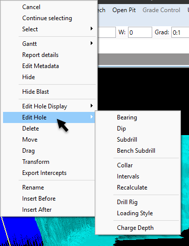
