Scanning Concepts |
Scan basics
Scan composition
A scan acquired with an R3 MkII scanner consists of a set of points measured by the laser rangefinder. For each point, the following information is recorded:
-
Azimuth: The direction the scanner head is facing when the point was acquired. This is also called the horizontal angle.
-
Elevation: The vertical angle of the laser beam that produced the point.
-
Colour: A colour value mapped from the photographic image (if applicable; the scanner must be equipped with a camera and photographic capture must be enabled).
In addition, the following information about the scanner is stored with each scan:
-
Position: The coordinates of the scanner origin (easting, northing, and elevation).
-
Bearing: The angle of the scanner’s forward direction relative to north.
-
Level correction: A correction applied to account for the inclination or tilt of the scanner’s vertical axis when its base is not perfectly level.
Position and orientation
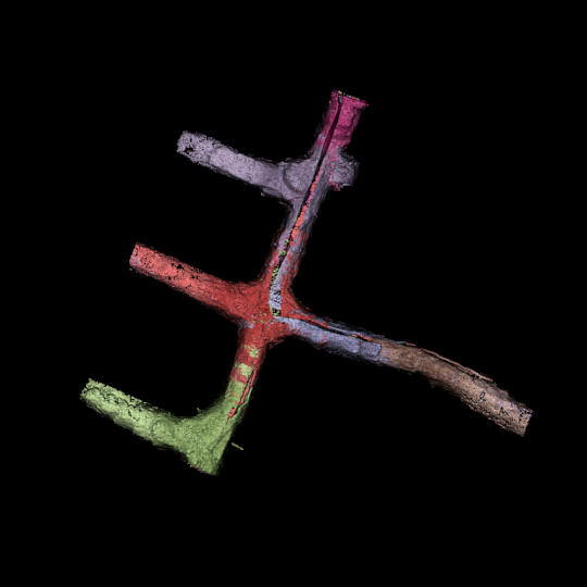
The spatial relationships between points within a single stationary scan are fixed and correct to within the tolerances of the scanner, regardless of whether the scanner location and orientation are known. For most practical applications, however, it is necessary to know the scanner’s precise position and bearing to locate and orient the scan correctly in a given coordinate system. This is especially critical in surveying applications where scans from multiple locations need to be integrated together, or where a scan needs to be compared against existing survey or design data.
There are multiple ways of locating and orienting scans correctly. These depend largely on the type of physical setup used to acquire scans. If a precise position and bearing are supplied when the scan is acquired (such as when scanning from a surveyed location and backsighting), the resulting scan will already be correctly located. If the position and bearing are inaccurate or unknown (such as when relying solely on the scanner’s internal GPS and compass), the scan will not be correctly located and will need to be positioned and registered using software tools. Positioning and registration is a process that can use both manual and automated methods to locate and orient scans correctly in space. Maptek FieldHHC has tools to help position and register scans in the field. Alternatively, desktop software such as Maptek PointStudio can be used for this process.

|
|
|
Figure 5-1 A set of underground scans before positioning (left) and after positioning and registration (right). |
|
The position and bearing of a scanner can be provided from the following sources:
-
Scanner internal GPS and compass
R3 MkII scanners are equipped with an internal GPS receiver and an internal compass, which together are capable of approximating the scanner’s position and bearing. The position and bearing are not generally accurate enough to rely on alone for surveying applications, but they can be used to roughly locate scans for subsequent adjustment using software tools.
-
An external survey-grade GPS receiver with an RTK fix can provide a more precise scanner position. When using FieldHHC to acquire scans, the GPS position can be obtained directly from a Bluetooth-connected GPS device mounted on top of the scanner, or can be manually entered. Position and bearing errors can be subsequently corrected using software tools. When using a survey-grade GPS, care must be taken to configure the GPS and FieldHHC to account for the vertical offset between the GPS position and the scanner reference level. See Calculating the GPS offset for detailed information.
-
A survey station database is a text file that contains a set of named coordinates corresponding to known reference locations. For typical survey jobs, the scanner is set up at a fixed surveyed location such as a bollard, and the bearing is established by backsighting to another surveyed location. For underground surveys, both the position and bearing of the scanner can be established by backsighting to three surveyed locations. To obtain an accurate backsight, the scanner must be equipped with a backsighting telescope (XR3-CT) or laser aimer (SR3).
-
If the scanner is mounted on a vehicle, a bearing for the scanner can be derived from the GPS track heading as the vehicle moves. Bearing errors can be subsequently corrected using software tools.
-
When scanning with Maptek Drive, an accurate position and bearing is provided in real time using the Drive INS and GPS systems.
Note: If no scanner positioning information is available, scans can still be acquired. The origin of scans will be recorded as [0, 0, 0]. Some applications (such as stability monitoring with Maptek Sentry) do not require the scanner position to be known. Scans without positioning information can be positioned as required using software tools.
Level correction
R3 MkII scanners automatically record the scanner’s vertical inclination and apply a level correction to scans. The level correction can be either fine or coarse:
-
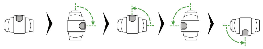
Fine levelling provides precise levelling of scans where the scanner’s inclination is within 5° of vertical. To achieve fine levelling, the scanner performs a highly accurate inclination check by traversing the scanner head in a specific sequence, shown in Figure 5-2. The resolution of fine levelling is 20″ increments.
-
Coarse levelling is used when the scanner is mounted at an oblique angle (greater than 5° from vertical). Typical situations include scanning into a stope or over the side of a gantry. When coarse levelling is applied, no inclination check is performed. The resolution of coarse levelling is 1° increments.
Note: Scanners mounted upside down and inclined within 5° of true vertical are automatically compensated in fine resolution.
Tip: You can choose between fine and coarse levelling when scanning with FieldHHC or with a mobile device. If fine levelling is selected but the scanner’s inclination exceeds 5°, coarse levelling will be applied.
Physical setup
R3 MkII scanners can be used in variety of physical setups, with different methods used for obtaining position and bearing information. The basic setup types are described below.
Fixed surveyed location
Scanning can take place from a previously surveyed fixed reference location such as a bollard. This job type uses the Survey Job setup in FieldHHC. The scanner position is typically set from a survey station database, but it can also be set from a survey-grade GPS position, or manually entered. Because the scanner’s reference level is usually offset vertically from the surveyed position, the scanner height needs to be entered in FieldHHC to correctly establish the scanner’s position. The bearing can be established by backsighting to another surveyed location. If there are no surveyed locations available to backsight to, the scanner’s internal compass can provide the bearing. See Setting up a survey job for how to set up a survey job in FieldHHC.
|
|
|
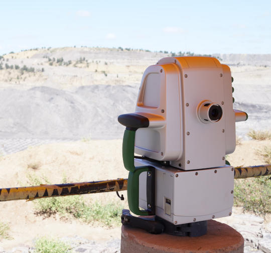
Figure 5-3 An XR3-CT mounted on a fixed bollard that has been previously surveyed. |
Tripod setup
Scanning can be performed using a tripod. The position and bearing of the scanner can be provided in one of the following ways:
-
Survey mark. If the tripod is set up over a survey mark, the setup is essentially the same as a fixed surveyed location as described above. The position can be supplied from a database and the bearing established by backsighting or using the scanner’s internal compass. The vertical offset from the survey mark to the scanner’s reference level needs to be entered as the scanner’s height (see Calculating the scanner height).
-
GPS. The position can be supplied from either the internal or external GPS. The bearing is supplied from the scanner’s internal compass. The setup type could be either a defined named setup or a survey job setup. See Setting up a scan job for more information.
-
Multiple backsights. When scanning underground from an unknown location, the position and bearing of the scanner can be derived by backsighting to three surveyed locations such as survey marks. See Setting up a survey job with multiple backsights for more information.
|
|
|
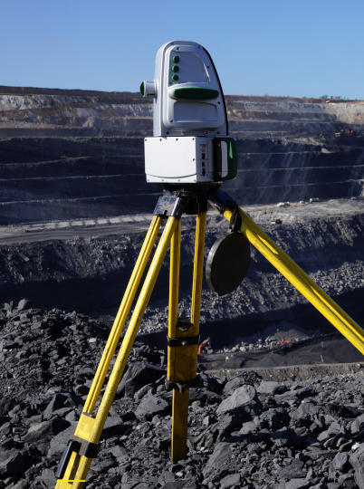
Figure 5-4 An XR3-CT mounted on a tripod |
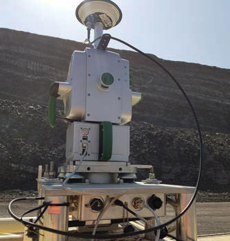
Vehicle mount
A vehicle mount enables stationary scans to be acquired from a vehicle. In this setup, the scanner position can be provided from either the internal or external GPS. The bearing can be supplied from the scanner’s internal compass, or alternatively the vehicle’s GPS track. Vehicle-mounted scanning typically uses the Defined Name setup type in FieldHHC (see Setting up a scan job).
|
|
|
Figure 5-5 A vehicle-mounted scanner with external GPS. |
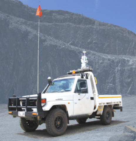
Note: The scanner’s internal compass bearing can be affected by interference from the vehicle’s metallic parts. When using the vehicle mount and relying on the scanner’s internal compass, the vehicle compass calibration factor should be enabled to compensate for this interference. The compass needs to be periodically recalibrated (see Calibrating the compass for vehicle use).
Maptek Drive
Maptek Drive is a system that allows scans to be acquired from a moving vehicle. Precise positioning and orientation information is provided in real time through the use of an INS (inertial navigation system). All Maptek R3 MkII scanners can be used with Maptek Drive; however, the XR3 dual window scanner is particularly well-suited for acquiring driving scans. When acquiring a driving scan, the scanner head does not traverse to acquire more points; instead, the scanner is mounted in a fixed position (usually facing out from the side of the vehicle) and acquires points as the vehicle moves. See Scanning with Maptek Drive for more information.
|
|
|
Figure 5-6 Maptek Drive system |
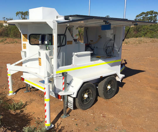
Maptek Sentry
All Maptek R3 MkII scanners can be used with Maptek Sentry to perform stability monitoring. Sentry continuously scans a scene from a fixed location to detect movement. Sentry does not generally need to know the position or bearing of the scanner to operate, but positioning can be applied when required. Consult the Sentry documentation for more information about Sentry.
|
|
|
Figure 5-7 Maptek Sentry DMS (Deployable Monitoring System) utilising an R3 MkII scanner. |
Defined name and survey job scans
There are two broad categories of scans, which depend on the physical setup of the scanner.
-
Defined name scans are scans taken from an unsurveyed location without any backsights. The physical setup is usually on a tripod or a vehicle mount. The bearing can either be supplied from the internal compass or derived from a vehicle’s GPS track. The position is supplied either by the scanner’s internal GPS or an external Bluetooth GPS. Drive scans acquired using Maptek Drive are defined name scans with bearing and position provided by the Drive INS and GPS systems. The filename of a defined name scan is based on a name supplied by the user. Defined name scans typically require registration to correctly locate and orient them.
See Setting up a scan job for more information.
-
Survey job scans are associated with a set of known scanner locations that are stored in a survey station database. A typical survey job involves setting the scanner up at a known location such as a survey bollard and backsighting it to another known location to establish a precise bearing. A special kind of survey job for use in underground situations uses multiple backsights to establish both the position and bearing of the scanner. The filename of survey job scans is based on the survey job name, the location name, and the backsight name or type.
See Setting up a survey job or Setting up a survey job with multiple backsights for more information.
Scanning settings
R3 MkII scanners have software-selectable settings that combine to affect the overall acquisition time and the quality of the resulting scan.
Scan mode
The scan mode sets the acquisition rate of the scanner. Physically speaking, it sets the frequency at which the laser pulses, which in turn affects the spinning speed of the scanning mirror and the traversal speed of the scanner head. Setting a faster scan mode reduces the overall scanning time, but at the cost of decreased range performance. See Range versus reflectivity for the range performance of your scanner model at various acquisition rates.
There are four named scan modes: normal, fast, rapid, and ultra. Normal (or fast for SR3 scanners) is the baseline scan mode that provides the highest quality results and the maximum range performance. Ultra provides the quickest scanning speed, but at the expense of maximum range. Each successive scan mode has an acquisition rate that is twice as fast as the previous mode. Scan modes can be abbreviated to a number that indicates how many times faster the speed is compared to normal speed, so 2x (fast) is twice as fast as normal, 4x (rapid) is four times as fast as normal, and so on. The specific frequencies used for each scan mode depends on the scanner model. Table 5-1 summarises this information.
| UR3 | XR3 | SR3 | |
|---|---|---|---|
| Normal (1x) | 40 kHz | 50 kHz | - |
| Fast (2x) | 80 kHz | 100 kHz | 100 kHz |
| Rapid (4x) | 160 kHz | 200 kHz | 200 kHz |
| Ultra (8x) | 320 kHz | 400 kHz | 400 kHz |
For long-range scans or when operating in sub-optimal conditions, consider using a scan mode with a lower acquisition rate (e.g. normal or fast) and increasing the point density to maximise performance.
|
|
|
Figure 5-8 (a) Reduced range resulting from a faster scanning speed and (b) Increased range resulting from a slower scan speed and higher point density. |
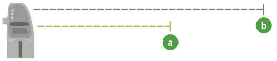
Tip: Scanning a smaller azimuth extent significantly reduces the overall scanning time when using scan modes with lower acquisitions rates. The elevation extent has no impact on scanning times.
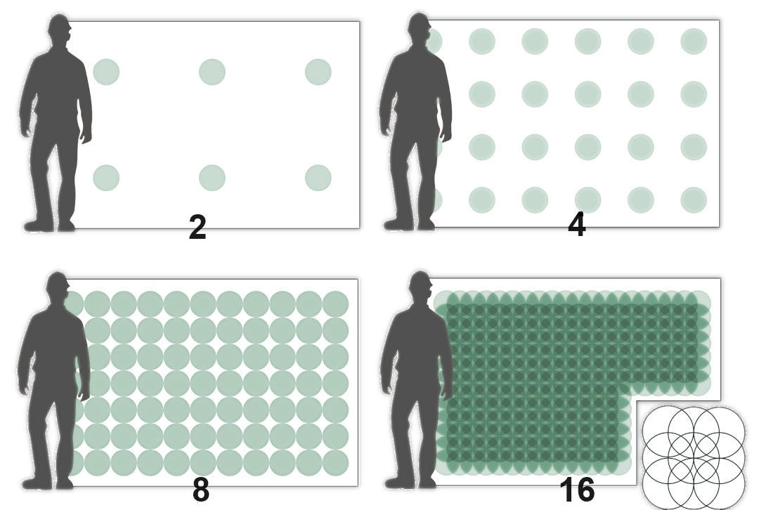
Point density
The point density is the resolution of the scan in terms of the horizontal and vertical angular spacing between neighbouring points. As with scan mode, the point density affects the traversal speed of the scanner head, so increasing the point density comes at the expense of overall scanning time. Increasing the point density increases the number of points and therefore increases the resulting scan file size.
Table 5-2 summarises the horizontal and vertical resolutions corresponding to each point density setting, and the resulting theoretical maximum point counts. The maximum point counts vary due to the different elevation ranges supported by each scanner model. In practice, scans will always have fewer points than the theoretical maximum. This is because not every pulse of the laser results in a return recorded, due either to the absence of reflective objects (sky points), or poor reflectivity of objects at a given range.
| Point density setting | Azimuth resolution (° per step) |
Elevation resolution (° per step) |
Theoretical maximum point count (millions of points)1 |
|||
|---|---|---|---|---|---|---|
| UR3 | XR3-C, XR3-CT, XR3-CD |
XR3-D | SR3 | |||
| 1 | 0.2° | 0.2° | 0.72 M | 0.81 M | 0.9 M | 1.17 M |
| 22 | 0.1° | 0.1° | 2.88 M | 3.24 M | 3.6 M | 4.68 M |
| 4 | 0.05° | 0.05° | 11.52 M | 12.96 M | 14.4 M | 18.72 M |
| 8 | 0.025° | 0.025° | 46.08 M | 51.84 M | 57.6 M | 74.88 M |
| 163 | 0.0125° | 0.0125° | 184.32 M | 207.36 M | 230.4 M | - |
Figure 5-9 gives a visual indication of the approximate point spacings of scan points using different point density settings.
|
|
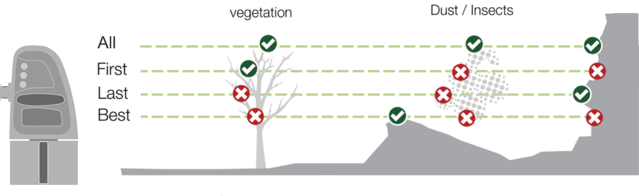
Scan point selection
Laser scanners work by measuring the time taken for a laser pulse emitted from the scanner to be returned after being reflected back by objects in its path. When the scanner emits a single laser pulse in a given direction, multiple returns can be received. This happens when the laser beam is partially obstructed by vegetation or airborne particles such as flying insects, dust, rain, or snow before reaching a terrestrial surface. The resulting scan can include points in space that are not associated with the surfaces intended for capture and are thus undesirable. To improve the clarity of the resulting scan, the signals returned to the laser rangefinder can be selectively filtered based on the time between the first and last return.
The scan point selection options are as follows:
-
Best uses an intelligent algorithm that selects the strongest returned point. This option is the default method and works well in most conditions.
-
First selects the first or closest points returned. If present, foreground obstacles such as vegetation or dust may predominate in the resulting scan.
-
Last selects only the last returned points. This option may improve results when scanning through vegetation, light dust, insects, or snow.
-
All saves the first, best, and last returned points.
Note: This option can produce scans with excessive data and large file sizes. Only use this setting when acquiring all points is necessary. Scans that save all points can be filtered in PointStudio using the Multi-Return Type filter.
Tip: When using FieldHHC, you can select which points are saved using the Points setting on the Acquire tab.
Scan file naming
When a scan is acquired from an R3 scanner, it is saved to a file named using a systematic scheme that encodes information about the scan.
The filename of a scan acquired from an R3 scanner has the following general form:
<name>_<speed><data><resolution><levelling><points>_<iteration>.r3s
where each component is defined as follows:
A scan file named 20240321 mtcarbo_ss32_ss21_4xC1L-B_01.r3s indicates the following:
-
The scan relates to the survey job named 20240321 mtcarbo, with its location set to survey station ss32, and was backsighted to the survey station named ss21.
-
4x means the scan was acquired with the Scan Mode set to Rapid.
-
C means both range and photo data was acquired.
-
1 means the Point Density setting was set to 1.
-
L means fine levelling was applied.
-
-B means the Points setting was set to Best.
-
_01 means it was the first scan taken with these settings.
A scan file named scan_2xR4U-F_02.r3s indicates the following:
-
The scan was a defined name scan using the name scan.
-
2x means the scan was acquired with the Scan Mode set to Fast.
-
R means only range data was acquired (no photographic image).
-
4 means the Point Density setting was set to 4.
-
U means either coarse levelling was applied, or the scanner was more than 5° off vertical.
-
-F means the Points setting was set to First.
-
_02 means it was the second scan taken with these settings.
Note: If a scan could only be partially completed, for example, because the scanner lost power mid-scan, the suffix _Incomplete will be appended to the filename.
Dual window scanning
The XR3 dual window scanner (XR3-D and XR3-CD) features a second scanning window at the back of the scanner. Dual window scanning allows data to be acquired from both the front and back windows simultaneously, providing for more efficient scan acquisition. The data acquired from each window is integrated into a single scan.
Dual window scanning can be enabled or disabled depending on requirements. When enabled, data is acquired simultaneously from both windows, allowing more data to be acquired in a shorter amount of time. The maximum range is capped to 600 m in this mode. When dual window scanning is disabled, data is acquired from the front scanning window only. This is useful when maximum range performance is required, as it effectively doubles the maximum range of the scanner (see Range versus reflectivity for details).
Tip: To enable dual window scanning in FieldHHC, tap the  (dual window mode) button in the view window on the Acquire tab.
Note: (XR3-CD only) Photographic imagery from the camera can be received through the front window only. If photo capture is enabled, photographic data will be rendered only to scan points acquired through the front window.
Dual window scanners are versatile and can be used for both mobile scanning with Maptek Drive and stationary scans, as follows:
-
Driving scan, dual-window mode
This is the most efficient way to acquire driving scans with Maptek Drive. Because data is acquired from both windows as the vehicle moves, there is no need for the vehicle to double back to scan the other side of the vehicle’s path.
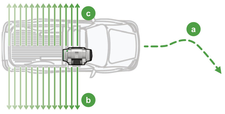
Figure 5-11 Acquiring a driving scan in dual-window mode

Vehicle path

Data acquisition from front window 
Data acquisition from back window -
Driving scan, single-window mode
If dual-window scanning is disabled, data will only be acquired from the front scanning window. The maximum range performance increases, but backtracking may be required to capture the full scene.
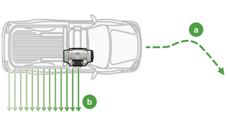
Figure 5-12 Acquiring a driving scan in single-window mode
Vehicle path
Data acquisition from front window -
Stationary scan, dual-window mode
Dual window scans can also be acquired from a stationary setup, such as a tripod or a stationary vehicle. In this case, the scanner head only needs to traverse 180° to capture a 360° scan, effectively halving the scan acquisition time.
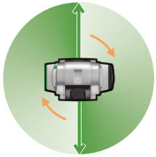
Figure 5-13 Acquiring a stationary scan in dual-window mode
-
Stationary scan, single-window mode
Dual-window scanning can be disabled when acquiring from a stationary setup to increase range performance. The scanner head traverses like an ordinary XR3 scanner to acquire data.
XR3 dual window scanners are calibrated to provide close angular data matching between the front and rear window scan data, but the following factors should be noted that may affect data matching:
-
Environmental factors, including vibration and temperature, can cause a small degree of offset to calibration values. This is a normal characteristic of the scanner operating within its manufacturing tolerances.
-
Angular offset may be more evident for data approaching maximum distances. Use the front window only option if the 180-degree data seam created between the front and rear windows is an issue.
