View Window Toolbars
Source file: view-window-toolbar.htm
The view window toolbar is used to modify the display of data in only the associated view window. The tools do not change the data itself.

Action plane group
The action plane group is used to
control the action plane in the
view
window. To learn more about the action plane group, click here.
Stereonet toolbar
The stereonet toolbar is used to control and modify a stereonet. It only appears when a stereonet is loaded in its own view window. See Stereonet Toolbar to learn more about the stereonet toolbar.
Conformance scene toolbar
The conformance scene toolbar is used for analysing conformance scenes. It only appears when a conformance scene is loaded in a view window. To learn more about the stereonet toolbar, click here.

Refer to the table below for descriptions of the remaining individual icons and their functions, as well as shortcut keys.
| Icons | Description | Shortcut |
|---|---|---|
|
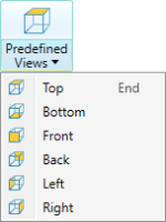
Predefined views:
Provides a choice of views of the scene from the main orthogonal
directions aligned with the axes (Top, Bottom, Front, Back, Left
and Right). The command provides two-stage
functionality, described below:
|
End |
|
|
Zoom to selection: The view window will zoom to include all the selected objects (without changing the camera direction). |
L |
|
|
Set camera view point: Displays the data from a defined position, towards a selected
orientation.
|
Shift+K |
|
|
Set centre of rotation: Moves the centre of rotation. Click on the button then in the new location. When rotating a view, the centre of rotation is at the position of the axes in the view window. Tip: If the axes are blocking data from view, right-click and select Show axes to deselect them. Select Show axes again to redisplay the axes. Alternatively, toggle A. |
C |
|
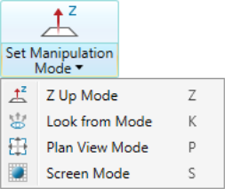
Set manipulation mode: Four manipulation modes are available to manipulate the
view of the data.
|
Z K P S |
|
|
Set projection mode: Toggles between orthographic and perspective projection.
|
8 |
|
|
Select all visible data: Selects all objects or primitives (based on the current selection mode). |
Ctrl+A |
|
|
Invert selection: Changes selection to all visible data that was not selected. |
I |
|
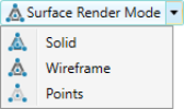
Surface render mode: Switches the rendering between solid, wireframe and points display. The selection affects all objects in the view window. |
G |
|
|
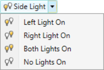
Set lighting state: Change the number of lights and light positions to alter scene lighting and subsequent shadow display.
|
Alt+4 Alt+5 |
|
|
Headlight toggle on/off: Turns the headlight on and off. The Headlight is a light aligned permanently with the camera direction. |
Alt+3 |
|
|
Toggles the overhead lighting on and off. |
|
|
|
Coordinate grid: Toggle display of coordinate grid. The grid is viewable only from above (looking down z axis) when in orthographic mode. The grid is auto-scaling and displays basic dimensions. To learn about creating a grid, see Grid. |
|
|
The action plane provides a mechanism to help place points in 3D space as well as set up a convenient 2D plane to perform 2D functions on. For detail on action planes, see Action Plane. |
|
|
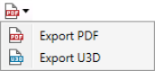
To learn about exporting 3D data, see Capture Scene. |
|
|
|
Image Render: Render a high resolution image of the view. To learn about rendering an image, see Capture Scene. |
|
|
|
Display animation editor: Set up and render animated scenes including data. To learn about creating an animation, see Animation Editor. |
|
|
|
Visibility editor: Displays a list of the contents of the view window, which can be hidden and redisplayed. To learn more about the visibility editor, see Visibility Editor. |
V |
|
|
Juxtaposition View: Splits the view in half for easy comparison of objects. To learn about using the juxtaposition view, see Juxtaposition. |
|
|
|
Tie to <view name>: Ties the active view to other view so that data manipulation functions on tied views simultaneously. For more detail, see Tying view windows together.
|