View window toolbars
Source file: view-window-toolbar.htm
View window toolbars are used to modify the display of data in only the associated view windows. The tools do not change the data itself.
The toolbar that appears depends on the types of data loaded in the associated view window. The toolbars available are summarised below.
View toolbar
The view toolbar duplicates most of the tools found on the View tab. These tools are described in the table below, with shortcuts where applicable.

| Icons | Description | Shortcut |
|---|---|---|
|
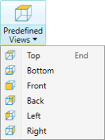
Predefined views:
Provides a choice of views of the scene from the main orthogonal directions aligned with the axes (Top, Bottom, Front, Back, Left
and Right). The command provides two-stage functionality, described below:
|
End |
|
|
Zoom to selection: The view window will zoom to include all the selected objects (without changing the camera direction). |
L |
|
|
Set camera view point: Displays the data from a defined position, towards a selected
orientation.
|
Shift+K |
|
|
Set centre of rotation: Moves the centre of rotation. Click on the button then in the new location. When rotating a view, the centre of rotation is at the position of the axes in the view window. Tip: If the axes are blocking data from view, right-click and select Show axes to deselect them. Select Show axes again to redisplay the axes. Alternatively, toggle A. |
C |
|
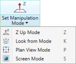
Set manipulation mode: Four manipulation modes are available to manipulate the
view of the data.
|
Z K P S |
|
|
Set projection mode: Toggles between orthographic and perspective projection.
|
8 |
|
|
Select all visible data: Selects all objects or primitives (based on the current selection mode). |
Ctrl+A |
|
|
Invert selection: Changes selection to all visible data that was not selected. |
I |
|
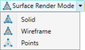
Surface render mode: Switches the rendering between solid, wireframe and points display. The selection affects all objects in the view window. |
G |
|
|
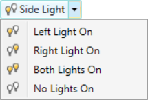
Side Light: Change the number of lights and light positions to alter scene lighting and subsequent shadow display.
|
Alt+4 Alt+5 |
|
|
Headlight toggle on/off: Turns the headlight on and off. The Headlight is a light aligned permanently with the camera direction. |
Alt+3 |
|
|
Toggles the eye-dome lighting on and off. |
|
|
|
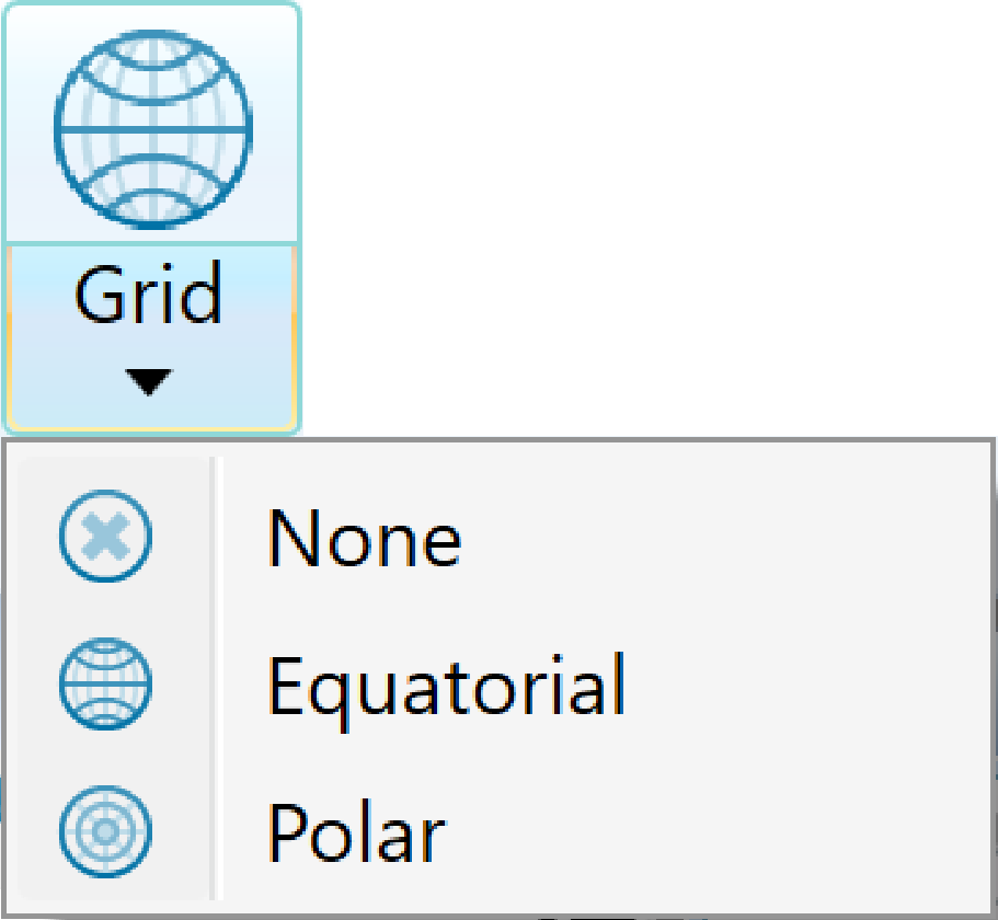
Coordinate grid: Toggle display of coordinate grid. The grid is viewable only from above (looking down z axis) in orthographic mode. The grid is auto-scaling and displays basic dimensions. To learn about creating a grid, see Grid. |
|
|
Action plane group: Provides a mechanism to help place points in 3D space as well as set up a convenient plane to perform 2D operations on. For detail on action planes, see Action Plane. |
|
|
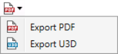
Export to: Create a file from the current view.
To learn about exporting 3D data, see Capture Scene. |
|
|
|
Image Render: Render a high resolution image of the view. To learn about rendering an image, see Capture Scene. |
|
|
|
Display animation editor: Set up and render animated scenes including data. To learn about creating an animation, see Export. |
|
|
|
Visibility editor: Displays a list of the contents of the view window, which can be hidden and redisplayed. To learn more about the visibility editor, see Visibility editor. |
V |
|
|
Juxtaposition View: Splits the view in half for easy comparison of objects. To learn about using the juxtaposition view, see Juxtaposition view. |
|
|
|
Tie to
|


Stereonet toolbar
When a stereonet is loaded in its own view window, the view window toolbar and the View ribbon will display stereonet and related tools.

The stereonet-specific tools are as follow:

Conformance scene toolbar
When you load the scene in a new view window, the view window toolbar is tailored with tools most relevant to managing the scene. These tools include several from the standard view window toolbar (see View), but with the different camera and scene controls described below.

| Icons | Description |
|---|---|
|
|
Set Camera as Default: Make the current direction and zoom the default view. |
|
|
View Camera Default: Return to the default viewing direction and zoom. |
The view window toolbar also provides the following tools with which you can query volume and distance conformance (see Design Conformance for more detail):
| Icons | Description |
|---|---|
|
|
Query Volume: Pick a region to report the underdig or overdig volume. |
|
|
Distance to Design: Pick a point to report conformance as distance from the design surface. |
When activated, these tools appear in the status bar. After picking points, click ![]() or press Enter to finish. Query results appear as annotations in the scene container.
or press Enter to finish. Query results appear as annotations in the scene container.
Note: The conformance scene view tab includes tools for changing annotation appearances (font size and colour) and for selecting the items to include in the distance to design annotation.
