Compositing
Use this option to average the assay values throughout a drillhole database. The database would typically contain core sample data at particular intervals of the geology, weathering, grade of ore, etc. The parameters defined through the Compositing option will be stored in a compositing specification file (.cm1).
The Compositing option combines a number of existing options under the Geology > Compositing submenu and displays them through a simple tree-control interface.
Tip: The compositing process can also be performed through a shell window by entering the following at the command prompt, as documented for the dbcmpt command-line program:dbcmpt specfile.cm1
where specfile.cm1 refers to the name of the compositing specification file.
Instructions
On the Geology menu, point to Compositing, then click Compositing.
Drillhole Database
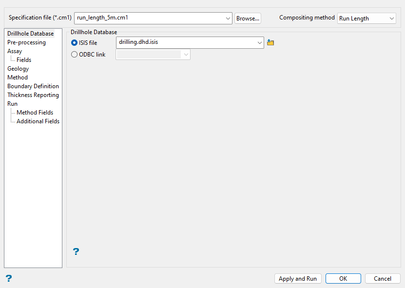
When the Compositing option is launched, start by populating the fields at the top of the panel to define the compositing specification file (.cm1) and compositing method, then go to the Drillhole Database section to select the database for compositing.
Follow these steps:
-
Select a Specification file (*.cm1) from the drop-down list, or enter a file name to create a new one. To select or create a specification file outside of the current working directory, click Browse....
-
Select a Compositing method from the drop-down list.
Vulcan offers several different compositing methods. Click on the sections below for descriptions of the available compositing method.
Note: Expected sample lengths with these methods may vary to respect the parameters set in the Geology or Boundary Definition panes.
 Straight
This method generates sample lengths that respect intervals in the selected assay field.
Use this method to obtain a samples database that respects the distribution of logged sample intervals.
Advantages:
-
Grade is not averaged between intervals; therefore, original data is preserved.
Disadvantages:
-
As values are not averaged, some may argue that the result is not really a composite.
Run Length
This method creates a composite that respects a defined length as measured down the drillhole trace.
Use this method when composites of exact length are required due to equipment constraints or mine design parameters.
Advantages:
-
Allows for exclusion of a range of assay values in pre-processing.
-
Various composite lengths are possible.
-
There are tools to ensure no small composite lengths generate.
Disadvantages:
-
May average grade across the defined length.
-
May artificially inflate the number of high grade samples.
Bench
This method is similar to Run Length compositing except the composite length is defined by a difference in elevation instead of a length measured along a drillhole trace. A single sample is generated at a defined bench height.
Use this method in open pit environments where knowledge of the average assay value of each bench is required.
Advantages:
-
Results are driven by mining parameters.
-
Resulting sample lengths respect bench heights instead of following the length of a curving exploration hole.
-
Works on mid-bench locations, which results in a single sample at a representative elevation.
-
Allows for exclusion of a range of assay values in pre-processing.
Disadvantages:
-
The option works on mid-bench elevations, which may not follow bench naming conventions at a site.
-
Composite lengths may not be equal due to downhole variation on individual holes.
-
Small composites may occur when the toe of a drillhole does not coincide with a bench toe.
-
The composite is based upon a single plane, so it assumes all benches are equidistant and have the same strike/plunge.
Inter Select
Short for Interval Selection, this method attempts to maximize the number of minable ore segments from a defined cutoff coupled with entered values for incorporating lengths of waste into composite intervals. The goal is to achieve the minimum grade required for mining. The intervals are coded accordingly in the
OREfield of the composite file.Use this method when an exact grade is required. Since the composite can be restricted spatially to account for minimum extraction capabilities of equipment, this option could be used for mine planning.
Advantages:
-
Special input parameters allow for more control over how the composite generates.
-
Optimizes each segment to achieve the defined grade.
-
Ore segments below the defined grade are flagged as waste.
-
There is control over how much, if any, waste is included in a sample interval.
-
Control over where waste is included in a sample interval: top, bottom, or both.
Disadvantages:
-
Longer compositing lengths are ultimately controlled by panel-defined restrictions; therefore, shorter compositing lengths are easily generated.
-
As the compositing is complex with exact results, many iterations are often required to achieve the required composite database.
-
As the program attempts to reach a specific grade, waste is added to high-grade ore. A relatively small, high-grade deposit can quickly, and artificially, spatially inflate because large amounts of waste may be added to achieve the defined cutoff grade.
-
Very high-grade, small deposits may be marked as waste if their size falls beneath defined parameters.
Geology
This method is similar to Straight compositing, except composite intervals are controlled by geology intervals instead of assay intervals. The length of the composite is controlled by the field defined as the Rockcode field through the Geology pane. Adjacent intervals of the same lithology are combined to establish the composite length.
Use this method if grade is controlled by lithology or if rock type is important to mineral extraction.
Advantages:
-
Allows for a single composite down adjacent intervals of the same lithology.
-
Respects geology intervals when rock type is important in the final model.
-
Allows for exclusion of a range of assay values in pre-processing.
Disadvantages:
-
Abnormally high or low assay values may artificially inflate or deflate the resulting geology composite length.
-
Blank values in the lithology field cause a break in the composite length; therefore, care must be taken to log all geology codes.
Minable Interval
With this method, compositing segments respect defined assay cutoff values as well as a defined segment length. Rock is classified and coded into three categories, as reflected in the
OREfield of the composite file:-
Waste, which is not represented in the resulting samples database.
-
Ore of acceptable length
-
Ore of unacceptable length
Use this method in large-scale mining operations where the scale of the equipment has a large bearing on the overall mine design and scheduling.
Advantages:
-
Can restrict the composite in such a way that resulting composites respect equipment used to extract ore.
Disadvantages:
-
Longer compositing lengths are ultimately controlled by panel-defined restrictions; therefore, shorter compositing lengths are easily generated.
-
As the compositing is complex with exact results, many iterations are often required to achieve the required composite database.
-
Minable Interval compositing parameters are more limited than the Inter Select method.
-
Small high-grade pockets are diluted with surrounding waste material.
-
Waste intervals are not written to the resulting sample database.
-
Selective interval method may cause more ore to absorb into waste intervals, which are not written to the output sample database.
-
-
Select the Drillhole Database to be used for compositing from the Isis file or ODBC link drop-down lists. To select an Isis file from a location other than the current working directory, click
 to browse to another location.
Pre-processing
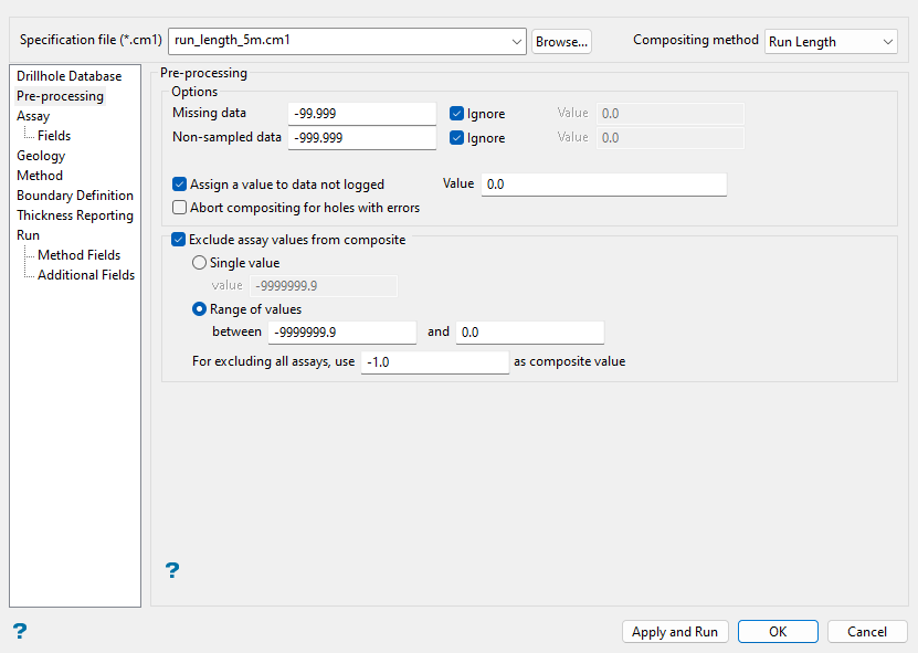
Use this pane to define how to handle missing or non-logged samples in the drillhole database. All of the compositing methods use the same pre-processing of the drillholes. The pre-processing step fills in any missing values at your request, and most importantly, breaks up the drilling based on various criteria. The compositing is then performed on the resultant drillhole segments.
Note: Zero length intervals are not included in the compositing process.
Important: Pre-processing settings are applied based on the first field defined in the Assay Fields table (see more information on the Assay and Fields panes in sections further below).
Follow these steps:
-
Enter the value that will be assigned to Missing data (only applies to assay values). You can choose to Ignore these assay values by selecting the respective checkbox, or you may substitute these values when compositing by entering a value in the Value field.
If you decide to ignore data, then the missing data values will not be used when compositing and will not be represented in the map file.
A    Missing data   0.000  Ignore Y   Value
B    Missing data   0.000  Ignore N   Value     0.000
C    Missing data   0.000  Ignore N   Value   -99.000
In case A, missing data values will not be used. In case B, the missing data values (
0.000) will be used. In case C, the missing data values will be replaced by-99.000. -
Enter the value that will be assigned to Non-sampled data. This is treated in the same manner as missing data. You can choose to Ignore these assay values by selecting the respective checkbox, or you may substitute these values when compositing by entering a value in the Value field.
If you decide to ignore data, then the non-sampled data values will not be used when compositing and will not be represented in the map file.
-
Select the Assign a value to data not logged checkbox if you would like to define a Value to be substituted in those intervals that were not assayed.
-
Select the Abort compositing for holes with errors checkbox if you want Vulcan to check for overlapping intervals and inverted holes. Drillholes that fail these validity tests will be excluded from compositing.
-
Select the Exclude assay values from composite checkbox to prevent selected assay sample values from being used in the composite. You can exclude either a single value or a range of values.
Note: This checkbox is only available for Run Length, Bench, and Geology compositing methods.
-
Single value: Select this option to define one assay value to exclude from the composite.
-
Range of values: Select this option to enter two assay values, the range between which will be excluded from the composite.
Tip: We recommend that you use the Range of values option to exclude assay values rather than a Single value to account for computer rounding (e.g. a single value of
-99will not pick up a value of-99.001).If all assays are within the exclusion range, the composite value will be set as defined in the For excluding all assays, use
-1.0as composite value field, where-1.0is the default.The total length of all samples is recorded, as well as the total length and average grade of the samples used. Here, 1 m samples will be composited over a 5 m bench. The default exclusion range is used:
>= -99999.000 and < 0.000.5 7 -1 3.2 7
The total length of all samples is 5. The total length of the samples being used is 4 (sample value
-1is not used because the exclusion range excludes the use of negative values). This length is stored in a new field calledLENG01or similar and can be used for weighting. The average grade of the samples being used is 5.5 (that is,5.5 = (5 + 7 + 3.2 + 7) / 4). If none of the sample values are being used, i.e. all values fall in the specified exclusion range, then a set composite value is used (default is-1.0). -
Assay
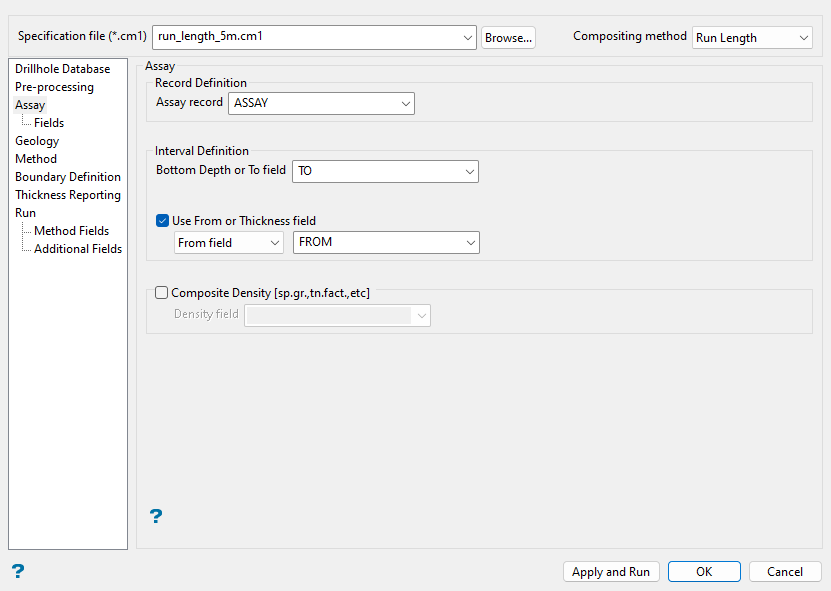
Use this pane to select the appropriate assay tables and header fields for the drillhole database.
Follow these steps:
-
Specify the database record table that contains assay data in the Assay record drop-down list.
-
Specify the field in the assay record table that defines the end of each interval in the Bottom Depth or To field drop-down list.
-
Select the Use From or Thickness field checkbox to define a From field or Thickness field. The field type and respective database field can be selected from the drop-down lists.
-
Select the Composite Density checkbox to composite a selected Density field in the drilling database.
Fields
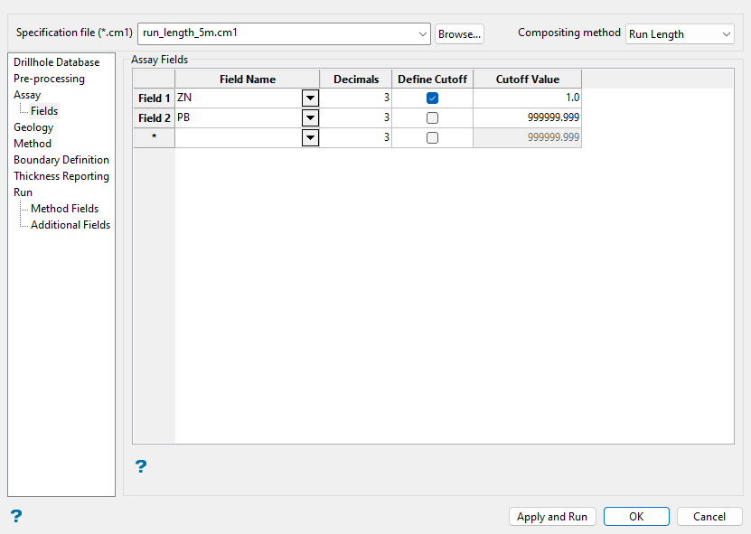
Use this pane to populate the Assay Fields grid with the applicable drillhole database assay fields and optional cutoffs.
Note: When computing statistics, the resulting field will add a two-character suffix to the end of each input Field Name of the Assay Fields table. As a field in an Isis database is limited to 6 characters, the resulting fields created from inputs with a field length longer than 4 characters will be truncated. This may result in several field headings that are indistinguishable from one another.
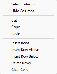
The panel utilises grid controls to manage the grid information, i.e. right-click context menus, that allow you to perform options such as hiding columns, cutting, copying, and pasting cells, and inserting and deleting rows. Right-click in the grid area to display the context menu. Descriptions of the available options are listed below.
-
Use the Select Columns option to choose which grid columns to display in the panel, and optionally save the selection to a template for future use. Alternatively, select cells and click Hide Columns to hide the respective columns directly.
-
Select cells and use the Cut, Copy, and Paste options to duplicate or move cell entries.
-
Select a cell in a row of interest and use the various insert and delete row options to manage the records in the grid.
-
Click Clear Cells to clear the contents of a selection.
Follow these steps:
-
Enter the Field Name of the desired assay fields for compositing. The names can be manually entered or selected from the drop-down list.
ImportantSettings in the Pre-processing pane are applied based on the first assay field that you define in this grid (Field 1).
In the case of the Inter Select compositing method, the length of the intervals is also determined from the parameters specified with respect to the first assay field in this grid. These lengths are then used for the other data fields. This allows you to identify the composite grade over the same intervals of the other elements in the deposit.
-
Enter the desired number of Decimals for the assay field data. You may set up to 6 decimal places.
-
Select the Define Cutoff checkbox if you would like to assign cutoff values for the specified assay fields.
-
Enter the desired Cutoff Value. Any assay value in the selected drillhole database field above this value will be set to the nominated cutoff value.
Three 2 m samples with the following assay values will be composited into a 6 m composite. The cutoff value is set to
10.0.1.0 5.0 35.0
The
1.0and5.0assay values are not altered because they are below the cutoff of 10.0; however, the35.0assay value is set to 10.0 due to this cutoff value. Therefore, the resulting composite equals 5.333 ((1.0 + 5.0 + 10.0) / 3).
Geology
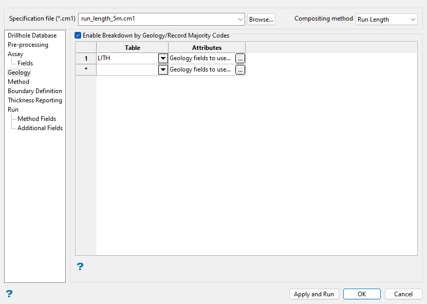
Use this pane to select geology records in the drillhole database to be considered, as specified, in compositing.
At least the minimum settings in the Geology pane must be set if using the Geology compositing method. This includes selecting the Table where lithology intervals are defined in the drillhole database and for Attributes, selecting a Rockcode field and Bottom Depth or To field.
Blank codes in the geology breakdown field are respected as if they represent a new type of geology.
The panel utilises grid controls to manage the grid information, i.e. right-click context menus, that allow you to perform options such as hiding columns, cutting, copying, and pasting cells, and inserting and deleting rows. Right-click in the grid area to display the context menu. Descriptions of the available options are listed below.
-
Use the Select Columns option to choose which grid columns to display in the panel, and optionally save the selection to a template for future use. Alternatively, select cells and click Hide Columns to hide the respective columns directly.
-
Select cells and use the Cut, Copy, and Paste options to duplicate or move cell entries.
-
Select a cell in a row of interest and use the various insert and delete row options to manage the records in the grid.
-
Click Clear Cells to clear the contents of a selection.
Follow these steps:
-
Select the Enable Breakdown by Geology/Record Majority Codes checkbox to populate the grid.
-
Enter the name of the Table in the drillhole database that contains the geological data. The name can be manually entered or selected from the drop-down list.
-
Click
 to configure the Attributes parameters through the Geology Fields To Use panel.
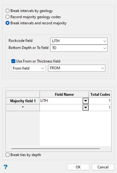
-
In this panel, select one of the following options:
-
Break intervals by geology: Select this option to create a composite split at a specific geological boundary.
This option may override parameters set in the Method pane in order to break the composite interval at a change in the defined Rockcode field. This may result in small composites, but could help ensure samples identify with a given lithology when estimating the block model. The rockcode for each interval writes to the GEOCOD field in the composite file.
Note: If the Run Length compositing method is used and the rockcode field breaks the intervals at a location that is not at a run length multiple, the run length of that group of lithology intervals will attempt to be as close to the run length as possible, depending on pre-processing selections and small composite settings.
-
Record majority geology codes: Select this option to record the majority code of a selected field present within a composite interval as well as the percentage of the composite length that consist of the majority code. The majority field grid at the bottom of the panel refers to the names of the fields containing the majority codes to use.
Parameters set in the Method pane are respected, but Boundary Definition parameters (if present) may still result in small composites. The majority code in the composite interval writes to a field in the composite file named after the majority field (e.g.
LITH). The percentage of the composite length that consists of the majority code is also written to the composite file in an associated field named after the majority field with a two-number suffix at the end (e.g.LITH01), numbered per the majority field sequence in the grid at the bottom of the panel.Note: As the fields in a composite file are limited to six characters, the resulting fields created from majority field lengths longer than four characters will be truncated in order to include the two-number suffix. This may result in several field headings that are indistinguishable from one another.
-
Break intervals and record majority: Select this option to break intervals by geology and record majority geology codes.
The aforementioned
GEOCODand majority geology code fields generate to the composite file.
-
-
Enter the name of the Rockcode field from the drillhole database that contains the geology rockcode. The name can be manually entered or selected from the drop-down list. This mandatory field allows a composite split at the boundary defined by the geological field in the database.
-
Enter the name of the Bottom Depth or To field from the drillhole database that contains the field that defines the end of each interval.
-
Select the Use From or Thickness field checkbox to define a From field or Thickness field. The field type and respective database field can be selected from the drop-down lists.
-
Enter the Field Name for the desired majority fields. The names can be manually entered or selected from the drop-down list. Create additional rows to add additional majority fields.
NoteThis grid is only available with the Record majority geology codes or Break intervals and record majority options.
For each majority field code defined in the grid, two new fields will be added to the composite file; the first stores the majority code, while the second stores the percentage of that code in the composite interval. If the Total Codes field is increased from
1for a majority field in the grid, two new fields will be created in the composite file for each code to list subsequent majority codes of the selected field, if present, and associated percentages.If a drillhole database has two different code values present in a field of interest within the composite length, the following results should be expected for the interval with each of the grid input cases shown:
Case 1:
Majority field grid inputs:
Field Name Total Codes Majority field 1 LITH 1 Resulting majority code fields for composite interval of interest:
LITH LITH01 TQ1 55.000 Case 2:
Majority field grid inputs:
Field Name Total Codes Majority field 1 LITH 2 Resulting majority code fields for composite interval of interest:
LITH_1ST LITH01_1ST LITH_2ND LITH01_2ND TQ1 55.000 TQ2 45.000 Case 3:
Majority field grid inputs:
Field Name Total Codes Majority field 1 LITH 3 Resulting majority code fields for composite interval of interest:
LITH_1ST LITH01_1ST LITH_2ND LITH01_2ND LITH_3RD LITH01_3RD TQ1 55.000 TQ2 45.000 NONE 0.000 -
Select the Break ties by depth checkbox to sort equal/tied values in a field by drillhole direction instead of alphabetically. Therefore, with the checkbox selected, if an interval contains equal proportions of two values, the value that occurs at the starting depth of the interval in the drillhole direction will be considered the majority. If the checkbox is not selected, the first geology value sorted alphabetically will be considered the majority.
-
Method
The options displayed in this pane of the Compositing interface change depending on the Compositing method selected. Click the sections below for steps to complete the Method options for the available compositing methods:
Note: No Method options are available with the Straight or Geology compositing methods.
Follow these steps:
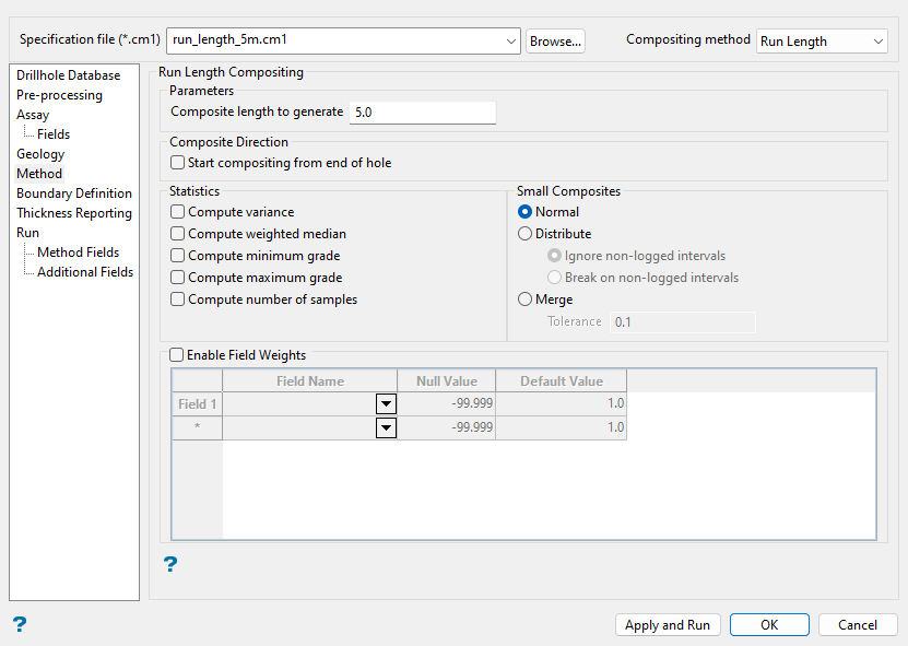
-
Enter a value for Composite length to generate to define the maximum length of the composite runs.
-
Select the Start compositing from end of hole checkbox if you want the compositing process to start from the end of each hole. Otherwise, compositing will begin from the start of each hole.
-
Select the Compute variance checkbox if you want Vulcan to calculate the composite variance. The variance is calculated by dividing the sum of the squares (of the differences between the value and the average) by n, where n = number of samples.
-
Select the Compute weighted median checkbox if you want Vulcan to calculate the weighted median of the samples that are used for each composite.
-
Select the Compute minimum grade checkbox if you want Vulcan to calculate the minimum grade for the composite.
-
Select the Compute maximum grade checkbox if you want Vulcan to calculate the maximum grade for the composite.
-
Select the Compute number of samples checkbox if you want Vulcan to compute the number of samples that are used for each composite.
-
Specify the approach that Vulcan will take with composites that are smaller than the standard interval by selecting one of the options in the Small Composites section. Small composites are sample lengths that are shorter than the defined run length due to drillhole geometry and/or set parameters.
-
Normal: Select this option to have small composites divided strictly by the run length. Pre-processing settings are respected.
-
Distribute: Select this option to have the length of the small composite divided equally amongst intervals of the same geology. Final sample lengths will be longer than the defined run length. You will also need to choose whether to composite any gaps together with the data, counting only the valid lengths (Ignore non-logged intervals), or to skip the interval (Break on non-logged intervals).
NoteIgnore non-logged intervals ignores any settings for missing data and non-sampled data defined in pre-processing to obtain the entire length of the drilled hole for distribution purposes. Values are inserted for all non-logged intervals.
When distributing composites with the Ignore non-logged intervals method:
-
Missing data and non-sampled data parameters configured on the Pre-processing pane are ignored. Address these values with Exclude assay values from composite options instead.
-
To control the value inserted in a composite for non-logged intervals, check Assign a value to data not logged on the Pre-processing pane and enter a Value. If a value is not entered on the Pre-processing pane, Vulcan uses surrounding interval values to populate non-logged intervals.
Break on non-logged intervals will restart the composite and distribution process at non-logged interval locations. Small samples are distributed to all resulting sample lengths before the non-logged interval, then compositing and distribution begins again after the non-logged interval. This means distributed lengths on either side of a non-logged interval may differ. Pre-processing settings are respected.
-
-
Merge: Select this option to add the last composite, if it is small enough, to the previous interval in the same geology. Pre-processing settings are respected. You will also need to define the Tolerance length. Anything less than the specified length tolerance will be added to the previous interval in the same geology.
-
-
Select the Enable Field Weights checkbox if you want to select fields to be used for weighting in the composite. Select the Field Name from the drop-down list that you want to use as the basis for weighting, the associated Null Value that is used for samples with missing data, as well as the Default Value to be used if a field value is not found for a given record. The weighting is also applied to the grade lengths stored in
LENG01or similar fields generated if the Exclude assay values from composite checkbox is enabled in the Pre-processing pane.
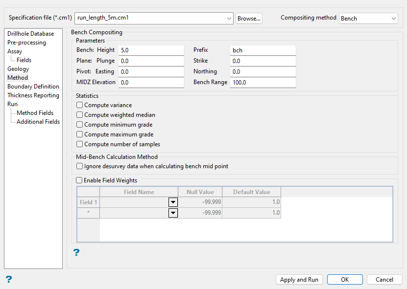
Follow these steps:
-
Enter the Height and Prefix values for the benches. The bench Height is measured in vertical elevation distance. Distance along the actual drillhole trace is not respected. If the drillhole is horizontal, tilted, or curved, the actual downhole length of the composite recorded in the composite file will be greater than the bench Height value. The Prefix value will be used to identify which bench goes with which hole.
-
Enter the Plunge and Strike direction values to define the plane to be used for the mid point of benching. Benching begins in the orientation of this plane.
-
Specify the origin of the plane in Easting and Northing to define pivot.
Note: Plane and Pivot values for Bench compositing are used in situations where existing pit designs or resulting block models are tilted. Choose a plane that represents mid-bench locations.
-
Enter the mid point Z elevation (MIDZ Elevation) of the composite. The first composite is created at the entered MIDZ Elevation, which should correspond to the mid-bench elevation in the pit design. The composite is calculated in the negative Z direction from the entered elevation at the entered bench Height. Choose a MIDZ Elevation that is above the highest composite point required.
-
Enter the Bench Range. This value allows you to define the relative distance from the mid plane down. Bench Range determines the range of the composite in the negative Z direction starting at the entered MIDZ Elevation.
-
Select the Compute variance checkbox in the Statistics section if you want Vulcan to calculate the composite variance. The variance is calculated by dividing the sum of the squares (of the differences between the value and the average) by n, where n = number of samples.
-
Select the Compute weighted median checkbox if you want Vulcan to calculate the weighted median of the samples that are used for each composite.
-
Select the Compute minimum grade checkbox if you want Vulcan to calculate the minimum grade for the composite.
-
Select the Compute maximum grade checkbox if you want Vulcan to calculate the maximum grade for the composite.
-
Select the Compute number of samples checkbox if you want Vulcan to compute the number of samples that are used for each composite.
-
Select the Ignore desurvey data when calculating bench mid point checkbox if you want to disregard any desurvey data when calculating the bench composite mid point.
-
Select the Enable Field Weights checkbox if you want to select fields to be used for weighting in the composite. Select the Field Name from the drop-down list that you want to use as the basis for weighting, the associated Null Value that is used for samples with missing data, as well as the Default Value to be used if a field value is not found for a given record. The weighting is also applied to the grade lengths stored in
LENG01or similar fields generated if the Exclude assay values from composite checkbox is enabled in the Pre-processing pane.
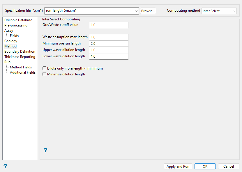
Follow these steps:
-
Enter the Ore/Waste cutoff value. Vulcan will assume that anything above the specified value is ore and anything below it is waste.
-
Enter the Waste absorption max length, which specifies the distance between any two ore runs that is the maximum waste that can be absorbed into one ore run as long as the composite grade remains above the Ore/Waste cutoff value.
-
Enter the Minimum ore run length to specify the length below which the run becomes a waste run. Any run below this length is automatically flagged as waste.
-
Enter the Upper waste dilution length and Lower waste dilution length, which are the maximum lengths of waste that can be added to the top and bottom (respectively) of an ore run as long as the composite grade remains above the Ore/Waste cutoff value.
-
Select the Dilute only if ore length < minimum checkbox to apply the upper and lower dilutions (only if it is necessary to achieve minimum ore run length).
-
Select the Minimise dilution length checkbox to dilute an ore run only until the run reaches the minimum length and not until the grade is at the waste cutoff.
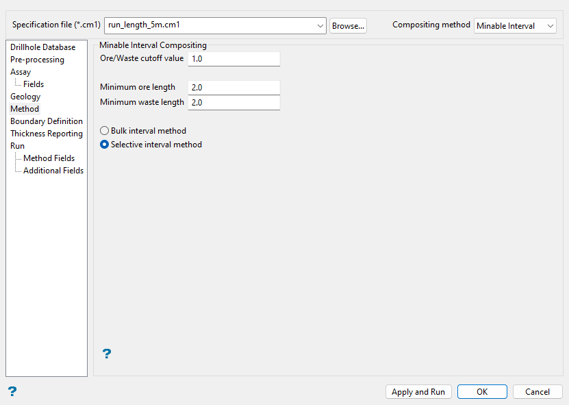
Follow these steps:
-
Enter the Ore/Waste cutoff value. Vulcan will assume that anything above the specified value is ore and anything below it is waste.
Enter this value for the mineral to be composited. Only one mineral can be composited at a time using this method.
-
Enter the Minimum ore length to specify the minimum length of ore necessary for the composite to be considered a minable ore run.
-
Enter the Minimum waste length necessary between ore runs for the ore runs to be considered minable.
-
Select between the available Minable Interval compositing method options of either Bulk interval method or Selective interval method.
-
Bulk Interval Method: This method creates the longest composite interval possible above the cutoff grade and adjusts the intervals below the minimum ore length, aiming to maximise the number of minable ore composites.
-
Selective Interval Method: This method is similar to the bulk interval method, except that it also considers the minimum waste length and adjusts the intervals again to increase the number of minable ore composites.
-
Boundary Definition
Use this pane to assign boundary codes to composites that lie inside/outside or above/below nominated triangulations.
Note: Defining boundary definitions will override the parameters set in the Method pane in order to break the composite at the boundary of the selected triangulations. This may result in small composites, but may help ensure samples identify with a given domain when estimating the block model.
The panel utilises grid controls to manage the grid information, i.e. right-click context menus, that allow you to perform options such as hiding columns, cutting, copying, and pasting cells, and inserting and deleting rows. Right-click in the grid area to display the context menu. Descriptions of the available options are listed below.
-
Use the Select Columns option to choose which grid columns to display in the panel, and optionally save the selection to a template for future use. Alternatively, select cells and click Hide Columns to hide the respective columns directly.
-
Select cells and use the Cut, Copy, and Paste options to duplicate or move cell entries.
-
Select a cell in a row of interest and use the various insert and delete row options to manage the records in the grid.
-
Click Clear Cells to clear the contents of a selection.
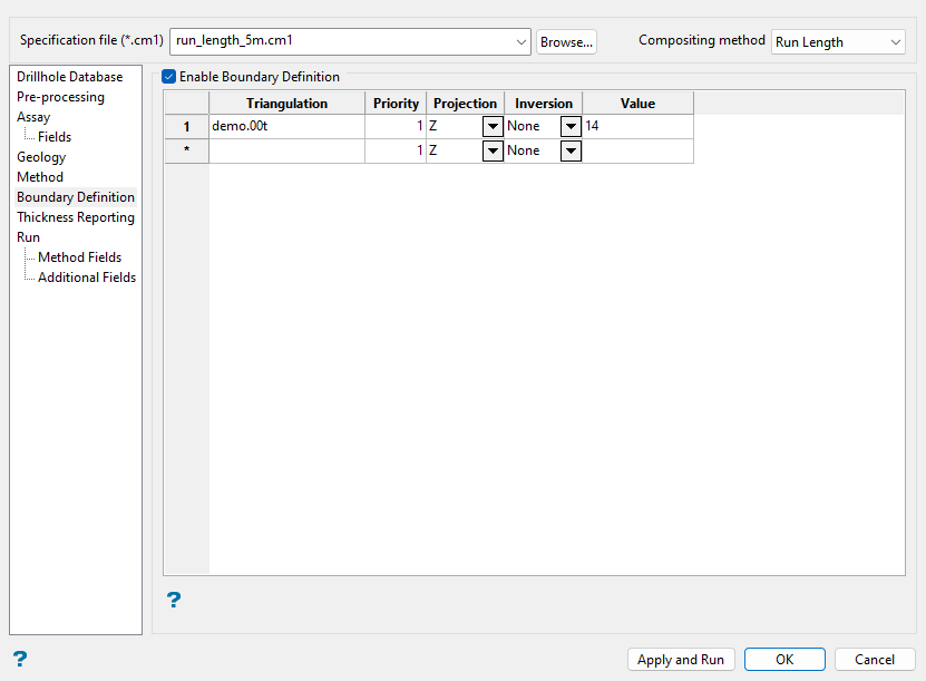
Follow these steps:
-
Select the Enable Boundary Definition checkbox to populate the grid.
-
Select a Triangulation to use for a boundary definition. The drop-down list contains all triangulations in the current working directory. Click
to select a triangulation file from a different location. -
Specify the Priority of the respective boundary definition. A definition with a higher value for the priority will override one with a lower priority
Example: A selected triangulation given a Priority of
10will override a triangulation with a Priority of1. -
Select the Projection axis from the drop-down list. You can choose from the X, Y, or Z axis to define the direction to project a surface. This option is useful in situations where steeply dipping structures define regions.
Note: The projection axis has no effect when working with solids.
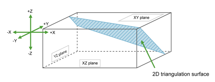
Figure 1 : Projection Axes
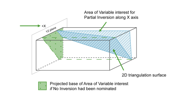
Figure 2 : Projection along the X Axis
For triangulations (ore bodies) that are steeply dipping, it may be necessary to project along the X or Y axis to ensure the correct inversion is applied.
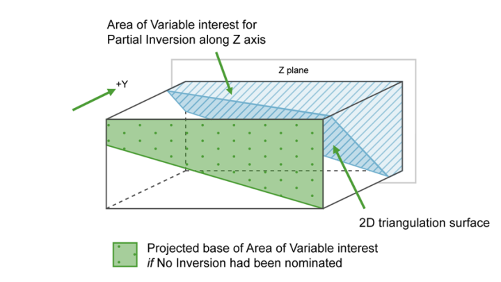
Figure 3 : Projection along the Y Axis
For triangulations (ore bodies) that are near to horizontal i.e. lying in the XY plane, you would project along Z axis. The area of interest is then below the triangulation (if None is selected for inversion) or above (if Partial or Complete inversion is selected).
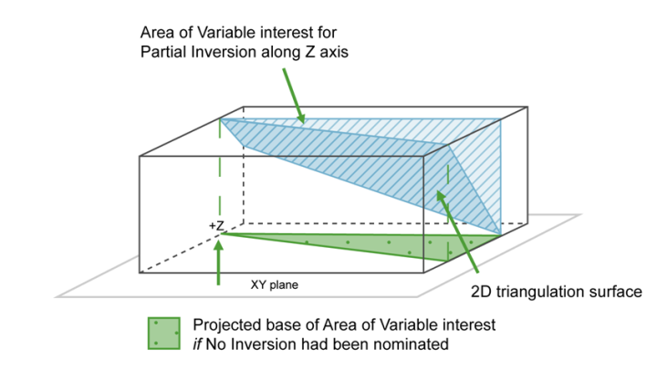
Figure 4 : Projection along the Z Axis
-
Select the Inversion method from the drop-down list. Choose from None (no inversion), Partial, or Complete inversion.
Note: Partial inversion has no effect for 3D triangulations (solids).
If None is selected, then the negative side of the triangulation is the area of interest.
If Partial or Complete inversion is selected, then the positive side of the triangulation is the area of interest.
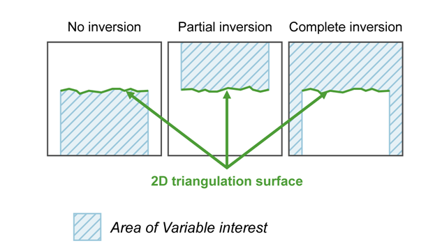
Figure 5 : 2D Triangulation Inversions
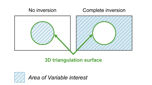
Figure 6 : 3D Triangulation Inversions
-
Enter the Value, which can be a number or character identifier, that will be stored as a character string in the
BOUNDfield of the composite file if the boundary definition is met, for example if the composite centre lies in a nominated triangulation, the nominated Value is then stored in theBOUNDfield.Note: Prior to version 3.2, this value was actually stored as a numeric value instead of a character string. Therefore, you will need to regenerate the
.cm1file as the older version 3.2 files will not work. Alternatively, you can manually edit the.cm1file and surround the value with quotes, for exampleVALUE="1.000".
Thickness Reporting
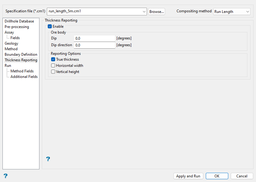
Use this pane to specify the orientation of the orebody and how you want the composite thickness to be reported (i.e. true thickness, horizontal width, or vertical height).
Note: The thickness reporting options are not applicable to the Minable Interval compositing method.
Follow these steps:
-
Select the Enable checkbox to use the thickness reporting options.
-
Enter the average Dip (measured in degrees from the horizontal) and Dip direction (measured in degrees clockwise from north) of the orebody.
-
Select the applicable Reporting Options for the thicknesses you would like to save to the composite file.
-
True thickness: Select this checkbox to save the length that is calculated for each composite from the downhole length in the direction perpendicular to the plane (average orebody orientation) specified by the orebody dip and dip direction. This composite thickness is then saved to the
TRUTHKfield in the composite file. The reporting of the true thickness can be used with a grid style estimation technique that estimates grade thicknesses. -
Horizontal width: Select this checkbox to save the horizontal component of the true thickness to the
HRZTHKfield in the composite file. -
Vertical height: Select this checkbox to save the vertical component of the true thickness to the
VRTTHKfield in the composite file.
Given a 10 m long composite from a vertical drillhole and an orebody dip of 60 degrees and direction of 135 degrees, the true thickness will be 5 m, the horizontal width will be 5.77 m and the vertical height will be 10 m.
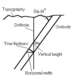
Figure 7 : Horizontal Width/Vertical Height
An orebody dip of 0 degrees will result in an infinite horizontal width and will be reported as -99. An orebody dip of 90 degrees will have the same effect for vertical height.
-
Run
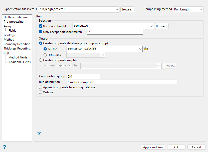
Use this pane to configure how the composite generation process will run.
If you are planning to dump the composites to a Vulcan samples database, then there are limitations on your composite settings.
The datasheet has a limit of 512 bytes per record. Of the 504 bytes that are actually available (the database record header uses 8 bytes), the mandatory composite fields (that is, the header with the ID_FIELD, etc. See Geology : Appendixes : B - Sampling Parameters : Common SMP Sections) require 140 bytes. This leaves 364 bytes for the user defined composite fields. The following algorithm can be used to calculate the number of bytes for the user defined composite settings:
Number of bytes = (number of assays) x 8
-
If you have selected true thickness, the number of bytes increases by 8 (number of bytes + 8).
-
If you have selected horizontal thickness, the number of bytes increases by 8 (number of bytes + 8).
-
If you have selected vertical thickness, the number of bytes increases by 8 (number of bytes + 8).
-
If you have selected use density, the number of bytes increases by 8 (number of bytes + 8).
If you have selected use majority codes:
-
Number of bytes = number of bytes + (number of majority codes) x 8.
-
Number of bytes = number of bytes + (number of unique numeric majority codes) x 8.
-
Number of bytes = number of bytes + (number of unique character majority codes) x 12.
-
If you have selected exclude values, the number of bytes = number of bytes + (number of assays) x 8.
-
If you have selected compute variance, the number of bytes = number of bytes + (number of assays) x 8.
The number of bytes = number of bytes + 140 (this is for mandatory fields)
If the number of bytes is greater than 504, an error will be generated.
Follow these steps:
-
Select the Use a selection file checkbox to limit the compositing to just those holes listed in an existing drillhole selection file (
.sel). The drop-down list contains all (.sel) files found within your current working directory. Click Browse... to select a file from another location.TipYou can create a drillhole selection file by selecting drillholes of interest, then right-click and select Drillhole > Selection File from the context menu to enter a file name and save the
.selfile for future use. This essentially creates a text file that contains a list of hole identifiers with the format shown below. You can also create a selection file manually using a text editor and saving the file with the.selextension. Note that drillhole names in the selection file are case sensitive.Drillhole selection file format:
DD00026
DD00035
DD00044
DD00053
DD00116
DD00143
-
Select the Only accept holes that match checkbox to limit the compositing to only those holes that match a specified name. Both the * (multiple character) and % (single character) wildcards may be used.
-
Choose between the options to Create composite database (e.g. composite.cmp) or Create composite mapfile.
-
Create composite database: Select this option to dump the composites into a database. You will then need to select between Isis file or ODBC link to create the nominated database type. Use the drop-down lists or the Browse... button to select an existing file, or enter a name to create a new file.
If you select to create an Isis file, keep in mind that although the drop-down list shows all database names, only a composite/samples database should be selected. To manually enter a new composite/samples database name, type the desired name, followed by a dot then a three-character composite extension of your choosing, and optionally a dot and the database identifier (i.e.
<database name>.<composite extension>.<isis>). The latter is only required if subsets of the database exist.Example: mydatabase.cmp.isis
-
Create composite mapfile: Select this option to dump the composites into an ASCII mapfile. The Optional mapfile identifier drop-down list contains all (
.map) files found within your current working directory. Click Browse... to select a file from another location. To create a new mapfile, enter a new file name.
-
-
Enter a name for the Compositing group (database index key) to which all composite information is related.
Example: Enter
RUN1to store composites built by a run length of 1 metre.This is especially useful for database composites as these may contain multiple sample groups. ASCII composite mapfiles may only contain a single group.
-
Enter text for the Run description to further describe the run. The maximum size is 40 alphanumeric characters.
-
Select the Append to existing compositing group checkbox if you want you to append the group to the same group of an existing database. This is only applicable when storing composites into an existing database. Since ASCII composite mapfiles only consist of one group, the compositing group specified above will overwrite the one in the existing ASCII composite mapfile.
-
Select the Verbose checkbox to generate a report for each hole, indicating the least (shallowest) dip for each hole during the selection process.
Method Fields
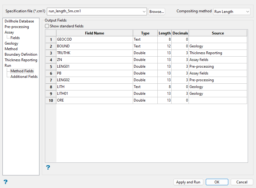
Use this pane to review the output fields for the composite file.
Note: You cannot edit these fields, here you may only view the list of fields that will be created for the composite based on the parameters set in previous panes of the Compositing interface.
Follow these steps:
-
Select the Show standard fields checkbox if you want to view all the standard database fields in the grid, otherwise only those that will be created from compositing will be listed.
-
Review the entries in the Field Name column understand which fields will be created from compositing.
-
Review the remaining columns including Type (data type), Length (character length), Decimals (pulled from settings in the existing database), and Source (pane of the Compositing interface that the composite field is generated from) to understand what data associated with each field.
Additional Fields
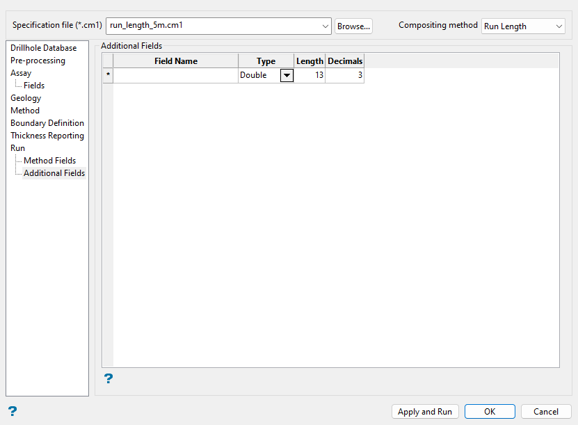
Use this pane to add additional fields to the composite file. You can populate these empty placeholder fields with various methods in Vulcan after the composite file is created.
Follow these steps:
-
Enter a Field Name for each new field.
-
Select a Type for the field data from the drop-down list.
-
Enter the Length for the field characters.
-
Enter the number of Decimals to use for the character field. Up to 6 decimal places may be used.
Running the compositing process
Click Apply and Run to save the current parameters and start the compositing process. Selecting the OK button will allow you to close the interface after saving the parameters. Click Cancel to close the panel without saving changes.
After selecting Apply and Run, a window displays in which the composite generation process is run.
Note: When compositing to a Vulcan or ODBC-linked database, the database must either be new or be compatible with the compositing parameter file being used. The first time a composite is run, assuming a database does not exist, the datasheet for that database is created and fields are established based upon specific parameters in the compositing specification file. If a specification file is changed so that it requires fields in the database that differ from those that currently exist, then a composite run to the already existing database will fail because it will not be compatible with the existing database's design sheet. In this case, either the existing datasheet will need to be modified to accommodate the new fields or the composite should be run into a new datasheet or one that has appropriate pre-existing fields.
Tip: To view composites, see guidance for Geology > Compositing > Display or Geology > Sampling > Load.

