Load and Display Drillholes
Use this option to load drillholes into Envisage.
Instructions
-
Select the database from the Vulcan Explorer, then drag the icon to the Envisage screen.
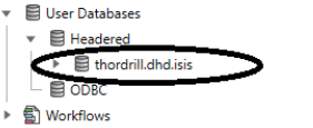
The following panel is then displayed.
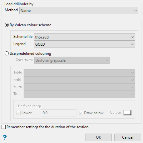
-
Select the method of displaying the drillholes by using the Method drop-down list. An explanation of each method is Use the drop-down menu to select the method to use for loading the drillholes..
-
Select the colour scheme by choosing either By Vulcan colour scheme or Use predefined colouring.
-
Click OK to display the drillholes.
Steps for loading by standard method
On the Geology menu, point to Drilling, and then click Load Drillholes.
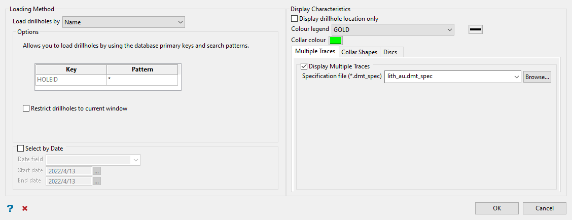
Note: Use the red x at the bottom of the panel to clear the parameters.
Steps
-
Use the drop-down menu to select the method to use for loading the drillholes.
The options in the Description section of the panel change depending upon the method used to load the drillholes.
 Name
Name
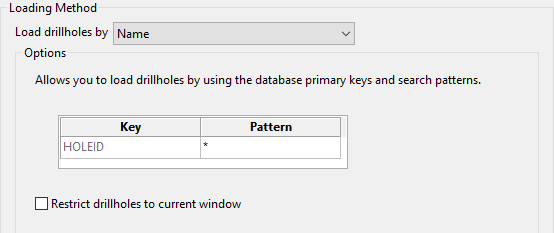
The number of fields displayed in the Key column depends on the currently opened database. For most drillhole databases, there will only be a single key field (the drillhole identifier).
Enter the name of the desired drillhole. Wildcards can also be used to load drillholes. An asterisk (*) represents all entries in a text field, and two decimal points (..) represents all entries in a numeric field. A question mark (?) can also be used to represent one or more characters in a text field.
Numeric Fields
number .. number
Restricts the objects to those between (and including) the two numbers, for example "50 .. 120".
number ..
Restricts the objects to those greater than or equal to the number, for example "25 ..".
.. number
Restricts the objects to those less than or equal to the number, for example ".. 34".
Text Fields
L* (multi-character wildcard)
Restricts the objects to those that begin with a specific letter, for example "L*" will load all drillholes that begin with "L".
L1? (single character wildcard)
Restricts the objects to those that consist of three characters, for example "L1?" will load all drillholes that begin with "L" and contain "1" as the second character.
Select Restrict drillholes to current window if you only want to load the drillholes whose collars fall in the current window coordinates. If this check box is not selected, then all drillholes will be loaded.
Note: This option only works in Plan view.
 Section

A section line must be created before using this option.
Only those drillholes with collars that are in the bounds of the section line will be loaded.
The section line must be created with only two points.
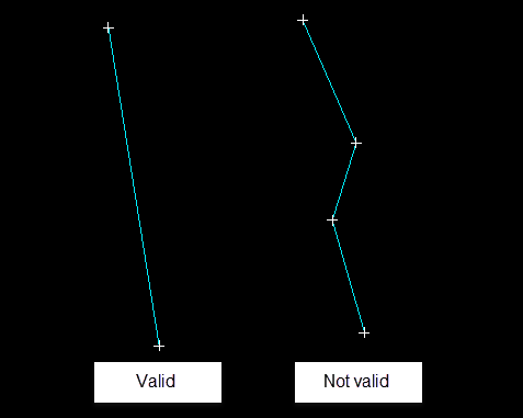
Section width
Enter the section width. This value refers to the distance in which the drillhole collar must fall in order to be selected. The selected section line lies in the middle of the specified width, i.e. a section width of 20.0 results in the loading of all drillholes that fall in 10.0 metres of either side of the section line..
You will then be prompted to select the section line.
 Polygon

A polygon must be created before using this option.
This method only works in Plan view.
Click OK to accept the panel.
You will then be prompted to select the necessary polygon.
The drillholes whose collars fall in the designated polygon will then be loaded. The number of drillholes loaded displays through the Report Window.
 Selection File

A drillhole selection file must be created before using this option.
TipYou can create a drillhole selection file by selecting drillholes of interest, then right-click and select Drillhole > Selection File from the context menu to enter a file name and save the
.selfile for future use. This essentially creates a text file that contains a list of hole identifiers with the format shown below. You can also create a selection file manually using a text editor and saving the file with the.selextension. Note that drillhole names in the selection file are case sensitive.Drillhole selection file format:
DD00026
DD00035
DD00044
DD00053
DD00116
DD00143
Filename
Specify the name of the selection file (
.sel). The drop-down list will contain all selection files found in the current working directory. Click Browse to select a file from another location. Exclusion File

Unlike the Load drillholes by Selection File method, which loads all of the drillholes listed in a nominated file, the Exclusion File method will exclude the listed drillholes from being loaded, i.e. only the drillholes that are not listed in the file will be loaded.
Like the Selection File method, the necessary file must be created before using this option.
TipYou can create a drillhole selection file by selecting drillholes of interest, then right-click and select Drillhole > Selection File from the context menu to enter a file name and save the
.selfile for future use. This essentially creates a text file that contains a list of hole identifiers with the format shown below. You can also create a selection file manually using a text editor and saving the file with the.selextension. Note that drillhole names in the selection file are case sensitive.Drillhole selection file format:
DD00026
DD00035
DD00044
DD00053
DD00116
DD00143
Filename
Specify the name of the exclusion file (.sel). The drop-down list will contain all exclusion files found in the current working directory. Click Browse to select a file from another location.
 Extent
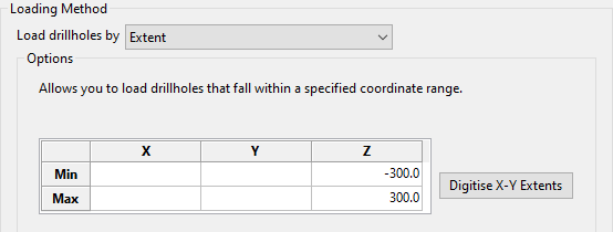
To display drillholes in a specific region, manually enter the minimum and maximum X, Y, and Z coordinates.
Note: Alternatively, to digitise a region on your screen in which drillholes are loaded, click Digitise X-Y Extents. The Z-values for this region must be manually configured in the Load Drillholes panel.
 Triangulation
Drillholes that intersect an open triangulation will be loaded.

If more then one triangulation is loaded, then you will be prompted to select the necessary triangulation.
 Filter
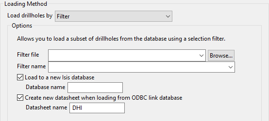
Selection filters are created through using the Selection Filter option. Unlike earlier versions of Vulcan, which used
.selffiles, the filters defined through Vulcan are now saved in a.slffile. Older selection files can be converted through using the Selection Filter option.Filter file
Browse to the desired
.slffile. This option is useful when multiple users need to use the same file.Filer name
Enter, or select from the drop-down list, the name of the selection filter (
.slf). The drop-down list contains all.slffiles found in your current working directory.Load to a new Isis database
Select this check box to load the selected database objects into a new Isis database (headered). If this check box is not selected, then the objects will be loaded onto the Vulcan screen.
Create new datasheet when loading from ODBC link database
Select this check box if you are loading from an ODBC link database into a new Isis database. A new design (datasheet), which has the same structure as the ODBC link database (minus the ODBC flag), will be created. If a new design wasn't created, then you would not be able to access the database because its design is linked to these ODBC parts.
-
Enable Select by date to limit the number of drillholes that are displayed by a starting and ending date. Only the drillholes that fall within these dates will be loaded.
-
Select Display drillhole location only if you only want to display the collar coordinates of the drillholes as points. These points will be stored in a temporary layer (DIG$DRILL). The options under Display characteristics are disabled when this check box is selected. If this check box is not selected, the entire drillhole trace will be loaded.
-
Use the Colour legend drop-down list to select a drillhole colour scheme.
-
You can also apply three additional display features.
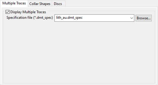
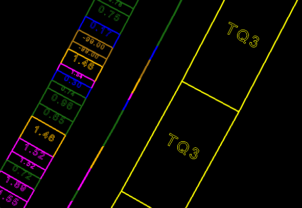
 Multiple Traces
Multiple Traces allows you to view additional drilling information along side the original drillhole trace when you are in section view.
Enable the option by clicking Display Multiple Traces. Select the specification file you want to use from the drop-down list, or by clicking the Browse button if it is stored in a location other than your current working directory.
Note: A Multiple Trace specification file needs to be setup before using this option. See Geology > Drilling > Multiple Trace Display.
 Collar Shapes
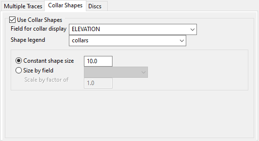
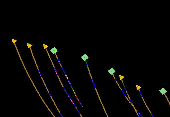
Collar Shapes allows you to insert a shape in place of the collar. This can be used to designate different elevations or levels, drillhole types, etc.
Note: To use this option, you must define the shapes by setting up a Shape legend in the Legend Editor.
 Discs
Discs
Apply cylindrical discs to the loaded drillhole traces by enabling Display drillholes as discs.
Note: You will need to select the existing scaled schema (SCALE) that defines the widths of the cylindrical discs from the Colour Legend drop-down.
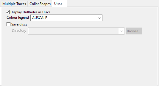
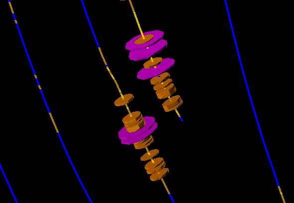
A message displays if there is a type mismatch between the chosen schemas. For example, a numeric schema is being used to colour the drillhole traces while an alpha schema is being used to control the width of the cylindrical discs.
Select Save discs to save the discs as triangulations. Select a location using the drop-down list, or browse for a location using the Browse button.
Click OK.
The drillholes are then loaded. The number of drillholes loaded will be displayed in the Report Window.

