Tutorial - Creating a Fan Variogram
Vulcan Data Analyser
T his tutorial provides step-by-step instructions on how to create a fan variogram. Fan variograms can be very helpful in determining the direction of greatest continuity for the Major, Semi-major and minor directions. This tutorial provides step-by-step instructions on how to create, display and save a variogram.
This tutorial uses a drillhole composite dataset which can be found here.
Opening Vulcan Data Analyser
- To begin, start Vulcan Data Analyser by launching Vulcan to the VDATutorial folder.
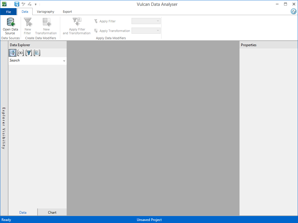
- On the Analyse menu, click Data Analyser. This opens up the main Vulcan Data Analyser window (VDA).
Loading your data
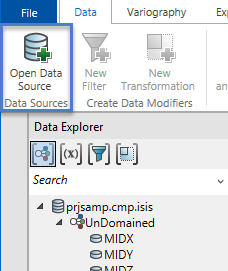
- On the Data tab, click Open Data Source. This will open a standard window's dialog where you may locate your desired file.
- Load prjsamp.cmp.isis.
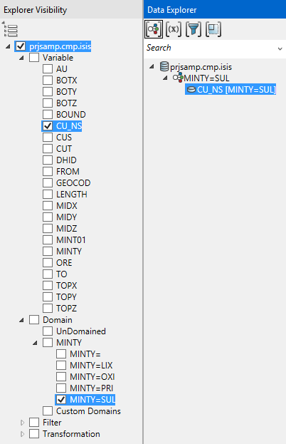
Suppose we want to model the CU_NS variable for the SUL domain. However, we don’t know the correct Major, Semi-major and minor directions. We can find out with a Fan Variogram.
-
Select the CU_NS [MINTY=SUL] data group.
Creating the fan variogram
The data is now loaded and ready to use in our analyses. Since we will not be altering the data we can begin creating the variogram.
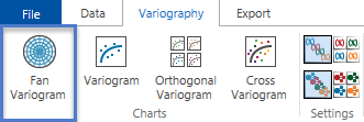
On the Variography tab, click Fan Variogram.
When you click Fan Variogram, the Properties panel on the right will populate as shown below. Leave all the default settings as they are and click the ![]() icon.
icon.
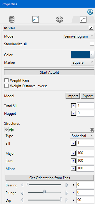
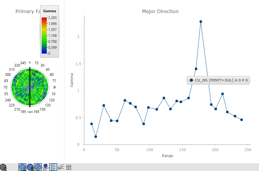
Now we see a Fan variogram for the selected data. On the left is a contour map for the gamma value of the selected variogram type (defaults to Semi Variogram). On the right you will see the variogram for the selected angle. You can change the selected angle with the angle selection tool on the fan. It is a thick black line. Using your mouse, you can click and drag the angle selection tool on the fan variogram and the variogram on the right will dynamically change.
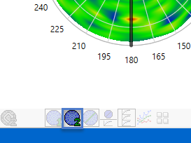
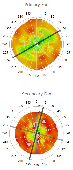
A fan variogram consists of a series of variograms in the primary plane and a second series in the secondary plane. By default, the second plane was generated normal to the first angle in the primary fan. To see the secondary fan, press the Second Fan button in the toolbar on the bottom of the fan variogram.
On the secondary fan the semi-major and minor directions are specified. You can change them by clicking and dragging the thick black line as in the Primary Fan. You can also view all of the primary and secondary variograms together or in a grid.
-
Collapse the data explorer by clicking on its top blue bar. This will give us some more screen space.
-
Also collapse the properties area.
-
Press the Multi Variogram button on the toolbar.

Now you see all the variograms together for the primary and secondary planes.
-
Close the Multi Variogram. Also close the Selected Variograms. This is done by pressing their buttons on the tool bar.
-
Now press the Variogram Grid button.
![]()
Now you see all the variograms in the primary and secondary planes. The current view does not indicate the primary directions for this data. This is because the default variogram parameters are not helpful.
-
Expand the properties area by clicking on the grey vertical bar that says “Properties”.
-
On the Variogram Parameters
 tab, change the lag size to 40.
 -
Change the Vertical and Horizontal tolerances to 10000.
-
On the Chart Setting
 tab, expand the Fan Axes group and uncheck Auto fit primary.
 -
Set the Primary max gamma to 1.
Notice that the colours in the Primary Fan have been rescaled so that 1 is now red. Numbers above 1 are grey.
-
Expand the Major axes and uncheck Auto fit.
-
Set the Maximum Y to 1.
Now the primary fan clearly indicates that 60 degrees is the primary direction. We need to specify this and regenerate the secondary data.
-
Remove the Variogram Grid and replace it with the Selected Variograms.
-
Use the angle selection tool to pick the 60 degree variogram.
-
Press the Set Secondary Plane button on the far left of the toolbar to compute the variograms perpendicular to the 60 degree azimuth.

-
Now set the Maximum Y values for the Semi and Minor axes to 1.
-
Also set the Secondary Fan max gamma to 1.
Now you can use the angle selector, grid view, and multi view to select the Semi and Minor angles.
Related topics

